
Phase locked loop circuit and clock reproduction circuit

a phase lock and loop technology, applied in the direction of pulse automatic control, digital transmission, oscillator generator, etc., can solve the problems of system instability, increase of jitter, and natural small circuit dynamic range, and achieve the effect of wide lock range, high gain, and increased vco gain

Inactive Publication Date: 2007-01-02
NEC CORP
View PDF8 Cites 9 Cited by
  • Summary
  • Abstract
  • Description
  • Claims
  • Application Information

AI Technical Summary

Benefits of technology

[0016]It is an object of the present invention is to provide a PLL circuit and a clock reproduction circuit which can operate stably with satisfying both of wide lock range and good jitter characteristics.
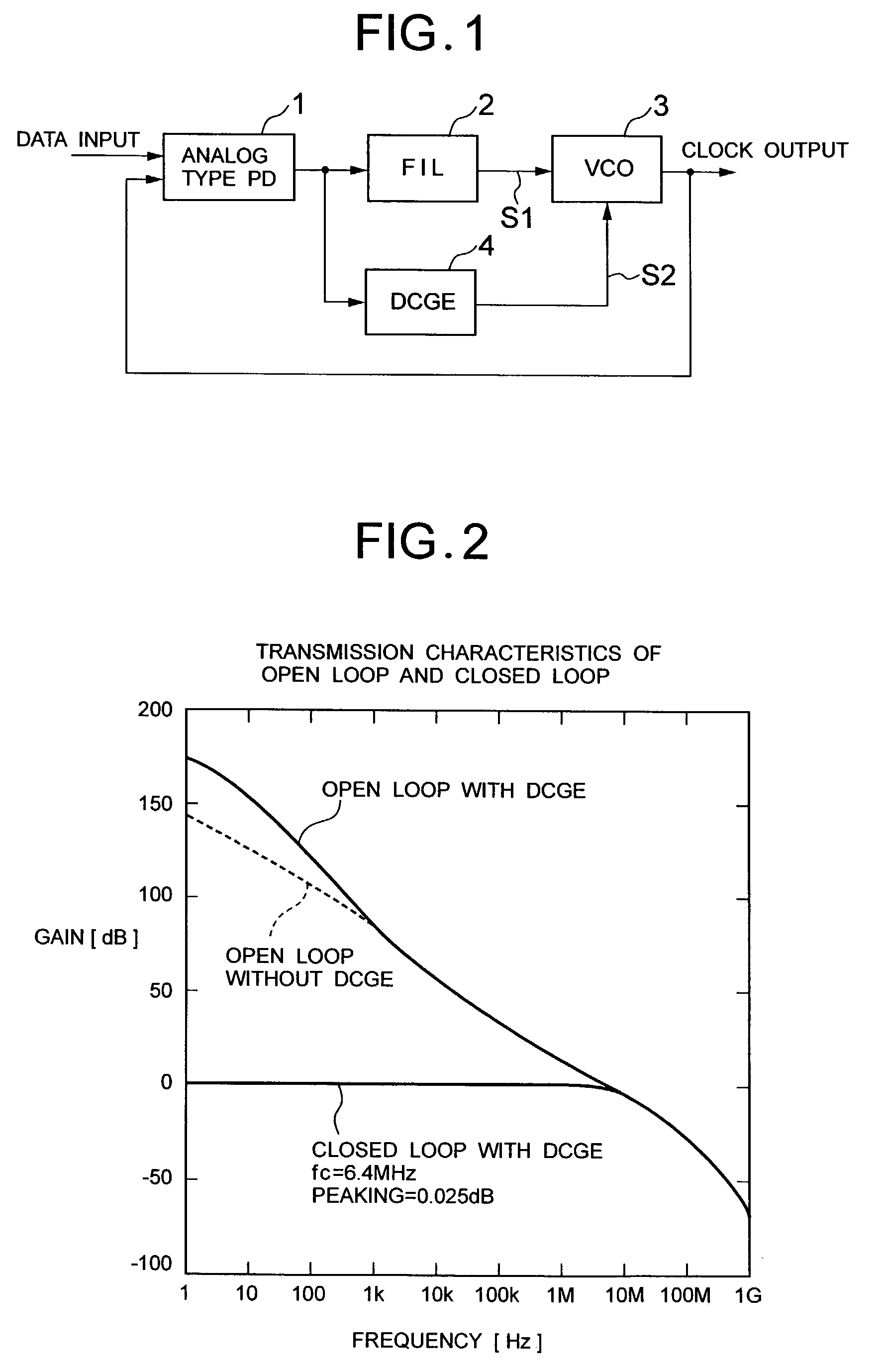
[0032]With this construction, in order to obtain the wide lock range, one of the control terminals of the dual-input VCO is provided high gain (increase the gain of VCO). By employing the narrow band direct current gain enhancer, high frequency noise component generated by the phase comparator can be sufficiently eliminated so as not to cause deterioration of jitter characteristics. Therefore, VCO gain of the low speed control loop via the direct current gain enhancer can set at higher gain than the VCO gain of the wide band high speed control loop via the loop file to permit widen variable range of the VCO without sacrificing the jitter characteristics. As a result, lock range can be widened.

Problems solved by technology

In such low voltage, a dynamic range of the circuit naturally becomes small.
However, when high gain as high as 1 GHz / V is provided as the gain for the VCO, it can quite sensitively follow to external or internal noise in steady operation state to cause increasing of jitter to make the system unstable.
As a result, difficulty is encountered in satisfying jitter specification of the SONET system set forth above.
However, in case of the digital phase comparator shown in FIG. 10B, since the gradient of the characteristics is infinite, the gain is theoretically infinite.
This means that the transmission characteristics of the closed loop of the PLL circuit can fluctuate to make the PLL circuit per se unstable to cause difficulty in satisfying the jitter specification (standard) in the SONET system.

Method used


Image

  • Phase locked loop circuit and clock reproduction circuit
  • Phase locked loop circuit and clock reproduction circuit
  • Phase locked loop circuit and clock reproduction circuit

Examples


Embodiment Construction

[0046]The present invention will be discussed hereinafter in detail in terms of the preferred embodiment of a phase locked loop (PLL) circuit and a clock reproduction circuit in accordance with the present invention with reference to the accompanying drawings. In the following description, numerous specific details are set forth in order to provide a thorough understanding of the present invention. It will be obvious, however, to those skilled in the art that the present invention may be practiced without these specific details.

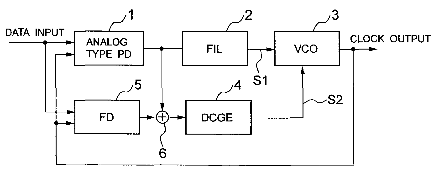
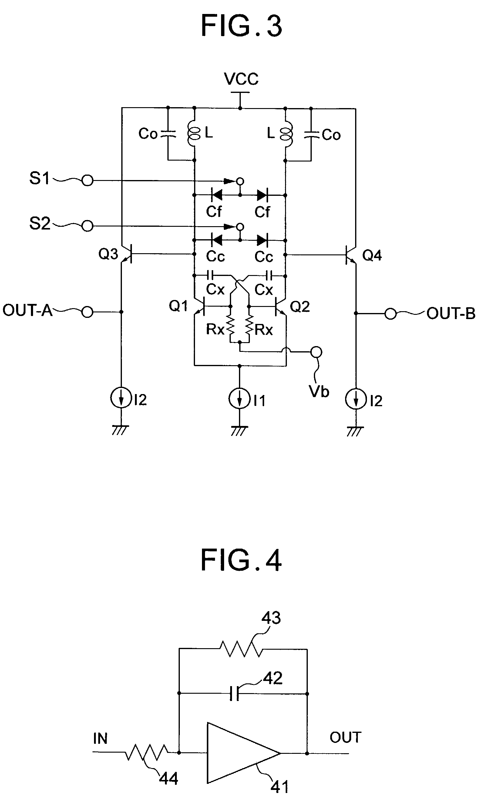
[0047]FIG. 1 is a block diagram showing a construction of one embodiment of the present invention. In FIG. 1, a phase comparator (PD) 1 takes an input data and an output signal (also serving as clock output) of a VCO 3 as two inputs to detect a phase difference between these two input signals. As the phase comparator 1, an analog type phase comparator is used. The analog type phase comparator has a phase difference detection output characteristics linear in a...


PUM


Abstract

A phase locked loop circuit and a clock reproduction circuit can operate stably with satisfying both of wide lock range and good jitter characteristics. The phase locked loop circuit for generating a clock signal in synchronized in phase with an input signal, has a phase comparator having an analog characteristics as a phase difference detection output characteristics and detecting a phase difference between the input signal and the clock signal, a first control loop controlled oscillation depending upon the phase difference detection output and a second control loop controlled oscillation depending upon a signal derived from the phase difference detection output with enhancing frequency components near a direct current component and performs low speed control in comparison with the first control loop.

Description

BACKGROUND OF THE INVENTION[0001]1. Field of the Invention[0002]The present invention relates to a phase locked loop (PLL) circuit and a clock reproduction circuit. More particularly, the invention relates to a PLL circuit generating a clock signal synchronized with an input signal in phase and a clock reproduction circuit using the same.[0003]2. Description of the Related Art[0004]In order to accurately reproduce a received data in a reception device in a communication system, it becomes necessary to extract a clock component synchronized with the received data. For extraction of the clock component and reproduction data, PLL circuits have been used widely.[0005]In SONET (Synchronous Optical Network) system as one of communication systems, a CDR (Clock and Data Recovery) circuit using the PLL circuit has been employed in order to reproduce a clock and a data. In order to adapt to a jitter specification (standard) in the SONET system, a frequency of a VCO (Voltage-controlled oscilla...

Claims


Application Information

Patent Timeline
Patent Type & Authority Patents(United States)
IPC IPC(8): H03D3/24H03B1/00H03B5/12H03L7/087H03L7/099H03L7/10H03L7/107H03L7/113H04L7/033
CPCH03L7/087H03L7/099H03L7/10H03B5/1243H03B5/1231H03B5/1215H03L7/113H03B2201/0208H03L2207/06H04L7/033
Inventor NOGUCHI, HIDEMI
Owner NEC CORP
Learn More