Efficient transplanter with pit digging devices
A transplanting machine, high-efficiency technology, applied in the field of transplanting machines, can solve the problems of inconvenient adjustment of plant spacing, poor versatility of transplanting machines, and inability to adjust the diameter and depth of digging pits, etc., and achieve easy operation, high degree of automation, and easy adjustment Effect
- Summary
- Abstract
- Description
- Claims
- Application Information
AI Technical Summary
Problems solved by technology
Method used
Image

Examples
Embodiment 1
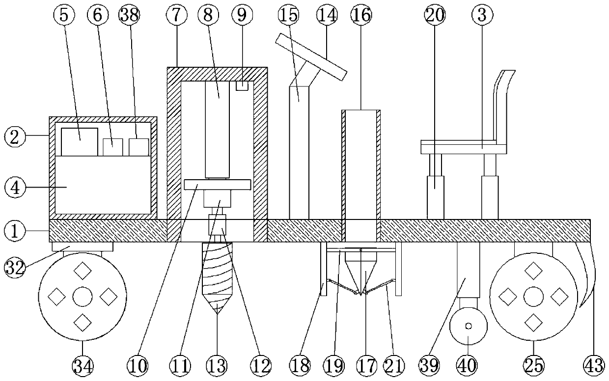
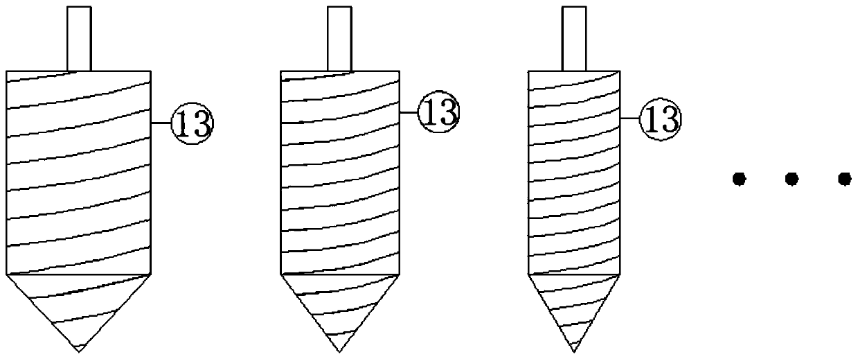
[0028] see Figure 1-8 , according to an embodiment of the present invention, a high-efficiency transplanting machine with a digging device includes a base plate 1, and the base plate 1 is provided with an electrical box 2, a digging device, a control device, and a transplanting device in sequence from left to right and the seat 3, a steering device is provided under the left end of the base plate 1, a driving device is provided under the right end of the base plate 1, a battery 4, a PLC controller 5 and a first driver 6 are fixed inside the electrical box 2, and the The digging device includes a cylinder 7, which is fixedly embedded on the bottom plate 1, and the inner wall of the upper end of the cylinder 7 is fixedly provided with a first hydraulic cylinder 8 and a distance sensor 9, and the first hydraulic cylinder A mounting plate 10 is fixed under the piston rod of 8, a rotating motor 11 is fixed under the mounting plate 10, a drill chuck 12 is installed on the rotating ...
Embodiment 2
[0031] see figure 1 , 2 and 7, for the steering device, the steering device includes a second bearing 32, the number of the second bearing 32 is two and are respectively fixed under the two sides of the bottom plate 1, and the inside of the second bearing 32 Both are fixedly provided with a second transmission shaft 33, the lower end of the second transmission shaft 33 is equipped with a steering wheel 34, the outer wall of the middle part of the second transmission shaft 33 is fixedly sleeved with a first gear 35, and the lower end of the bottom plate 1 is fixed. There are two second stepping motors 36 in quantity, and the outer wall of the rotating shaft of the second stepping motor 36 is fixedly sleeved with a second gear 37, and the first gear 35 is in phase with the corresponding second gear 37. engagement, the electrical box 2 is provided with a second driver 38, the second stepper motor 36 is electrically connected to the second driver 38, and the second driver 38 is e...
Embodiment 3
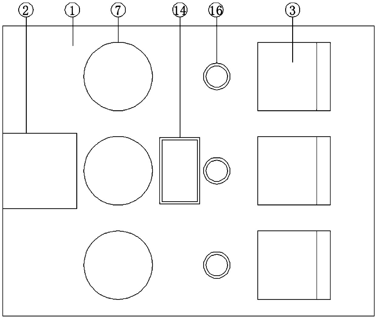
[0034] see figure 1 and 5 , for the electrical box 2, a door 41 is installed on one side of the electrical box 2 through a hinge, and a box lock and a handle are installed on the door 41; for the door 41, the upper end of the door 41 is opened There is a heat dissipation window 42, and a dust-proof net is fixed inside the heat dissipation window 42; for the base plate 1, two scraping plates 43 are fixed under the base plate 1, and the scraping plates 43 are connected to the bottom plate 1. The drive wheel 25 is matched; for the connecting piece, the connecting piece is a shock absorber 20, and the four corners of the seat 3 are fixedly equipped with a shock absorber 20, and the shock absorber 20 is fixed On the base plate 1; for the seat 3, the seat plate and the backrest of the seat 3 are fixedly provided with sponge pads.
[0035] Through the above scheme of the present invention, opening the box door 41 can facilitate the maintenance of the devices in the electric box 2, ...
PUM
 Abstract
Description
Claims
Application Information
 - R&D
- Intellectual Property
- Life Sciences
- Materials
- Tech Scout
- Unparalleled Data Quality
- Higher Quality Content
- 60% Fewer Hallucinations
Browse by: Latest US Patents, China's latest patents, Technical Efficacy Thesaurus, Application Domain, Technology Topic, Popular Technical Reports.
© 2025 PatSnap. All rights reserved.Legal|Privacy policy|Modern Slavery Act Transparency Statement|Sitemap|About US| Contact US: help@patsnap.com