Distributed 3D shape sensing demodulation method based on optical frequency domain reflection parameter optimization

A technology of optical frequency domain reflection and three-dimensional shape, which is applied in the direction of using optical devices to transmit sensing components, convert sensor output, and optical instrument testing. It can solve problems such as small strain and errors, and achieve accurate reconstruction and improved sensitivity. Effect

Active Publication Date: 2021-08-06
TIANJIN UNIV
View PDF6 Cites 0 Cited by
  • Summary
  • Abstract
  • Description
  • Claims
  • Application Information

AI Technical Summary

Problems solved by technology

However, there is a large error in the reconstruction of the shape with a large radius of curvature, which is due to the fact that the shape with a large radius of curvature induces less strain in the multi-core fiber
In addition, the OFDR system directly obtains the frequency shift information of the Rayleigh scattering spectrum, but the shape sensing requires the strain information of the multi-core fiber, and the calibration coefficient of the Rayleigh scattering spectrum frequency shift and the strain of the multi-core fiber needs to be calibrated. There will be large errors in the calibration process

Method used


Image

  • Distributed 3D shape sensing demodulation method based on optical frequency domain reflection parameter optimization
  • Distributed 3D shape sensing demodulation method based on optical frequency domain reflection parameter optimization
  • Distributed 3D shape sensing demodulation method based on optical frequency domain reflection parameter optimization

Examples


Embodiment 1

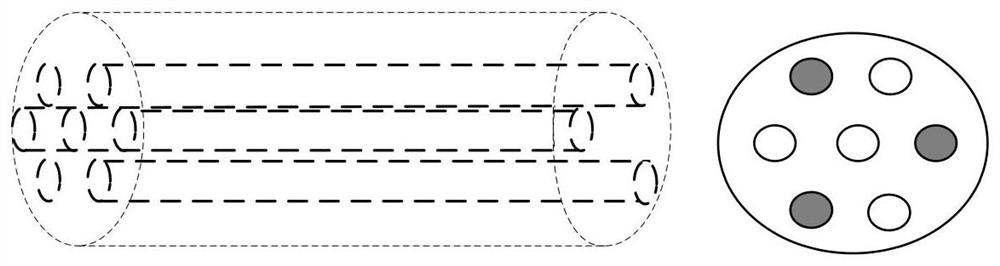
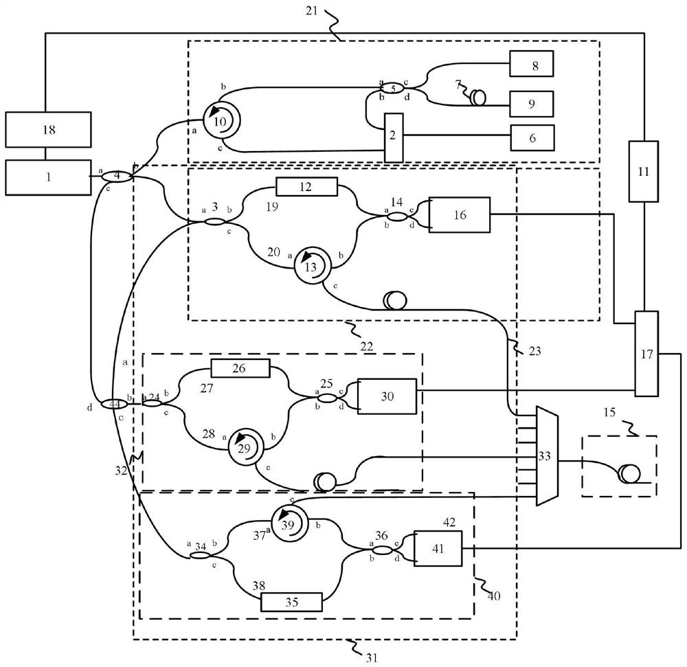
[0060] The present invention adopts three channels to demodulate a distributed three-dimensional shape sensing system in parallel. The optical fiber to be tested is a multi-core optical fiber. figure 1 shown. Distributed 3D shape sensing systems such as figure 2 Shown include:

[0061] The distributed three-dimensional shape sensing system mainly includes: tunable laser 1, 99:1 optical beam splitter 4, GPIB (general interface bus) control module 18, clock trigger device 21 based on auxiliary interferometer, main interference module 31, acquisition Device 17 , multi-core fiber fan-in and fan-out device 33 , multi-core fiber 42 and computer 11 .

[0062] The function of the tunable laser 1 is to provide linearly tunable laser for the whole demodulation device. The tunable laser 1 passes through the 99:1 optical beam splitter 4 and the clock trigger device 21 based on the auxiliary interferometer and the main interference module 31 . The clock trigger device structure 21 base...

Embodiment 2

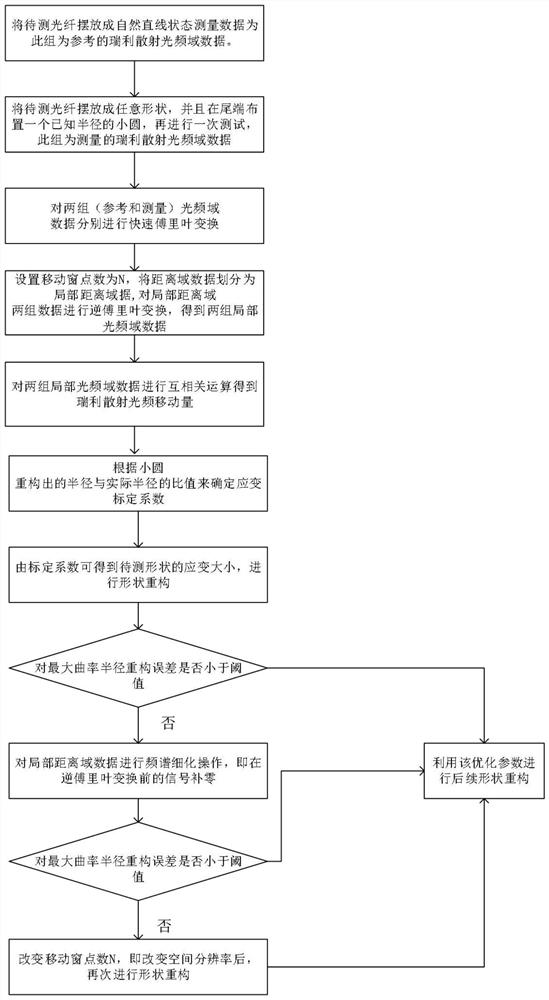
[0066] The invention provides a distributed three-dimensional shape sensing and demodulation method optimized for reflection parameters in the optical frequency domain, which is a sensing method for shape reconstruction by selecting a suitable Rayleigh scattering frequency domain refinement factor and spatial resolution. This sensing method is corresponding to the sensing system in embodiment 1, as image 3 As shown, the steps of a distributed three-dimensional shape sensing demodulation method optimized for optical frequency domain reflection parameters are:

[0067] In the first step, the distributed 3D shape sensing system is used to measure twice, one for reference data and one for measurement data. For the first measurement, place the part of the optical fiber to be tested in a natural straight line. For the second measurement, the optical fiber to be tested is placed in a certain shape, and laid into a circle with a radius of 5 cm at the end.

[0068] In the second ste...


PUM


Abstract

The invention relates to a distributed three-dimensional shape sensing demodulation method based on optical frequency domain reflection parameter optimization, which comprises the following steps: using a distributed three-dimensional shape sensing system to perform two measurements, and for the first time to place the part of the optical fiber to be tested In the state of a natural straight line, the frequency domain data of the Rayleigh scattered light measured this time is the reference data; the second time, the multi-core fiber to be tested is placed in any shape, and a small circle with a known radius is arranged at the end of the multi-core fiber. The Rayleigh scattered light frequency domain data measured at this time is recorded as measurement data; fast Fourier transform is performed on the reference data and measurement data; the inverse Fourier transform is performed on the local distance domain signals of the two groups of data; The ratio of the reconstructed radius of curvature to the actual radius of curvature is used to determine the calibration coefficient of the Rayleigh scattering spectrum frequency shift and strain of the entire measurement system in this state; Process to get the strain size, reconstruct the shape, and check the error.

Description

technical field [0001] The invention relates to the technical field of optical fiber shape sensing, in particular to a distributed three-dimensional shape sensing system and method. Background technique [0002] Optical fiber shape sensing is a sensing technology that uses the strain data measured simultaneously by optical fiber to restore the shape of the monitored object through a special algorithm. Due to its unique features of minimal interference and almost no weight, it has been widely used in two-dimensional or three-dimensional positioning, such as minimally invasive surgical catheter or flexible needle tracking, and structural health monitoring, aerospace. Looking at the research on optical fiber shape sensors at home and abroad, it can be seen that researchers mainly focus on the type based on FBG, but there are shortcomings in long-distance sensing; another type based on distributed Brillouin optical time domain analysis The optical fiber sensing technology of ad...

Claims


Application Information

Patent Timeline
Patent Type & Authority Patents(China)
IPC IPC(8): G01D5/353G01M11/00
CPCG01D5/35361G01D5/3538G01M11/331
Inventor 刘铁根丁振扬郭雅美刘琨江俊峰王晨欢陈泽恩
Owner TIANJIN UNIV
Why Eureka
Try Eureka