Scrap iron pressing device of machining center

A technology of a pressing device and a machining center, which is applied to metal processing equipment, metal processing machinery parts, presses, etc., can solve the problems of small amount of manual intervention, increased labor intensity, and pollution of occupied space, so as to improve environmental quality and save The effect of manipulating the space and improving the separation effect

Pending Publication Date: 2020-02-18
广州市永汇自动化设备有限公司
View PDF0 Cites 4 Cited by
  • Summary
  • Abstract
  • Description
  • Claims
  • Application Information

AI Technical Summary

Problems solved by technology

[0002] With the development of processing technology, machining is gradually carried out by machining centers, which are characterized by high machining efficiency, high precision, and small amount of manual intervention. It contains a lot of coolant (cutting fluid), and the waste chips enter the filter screen

Method used


Image

  • Scrap iron pressing device of machining center
  • Scrap iron pressing device of machining center
  • Scrap iron pressing device of machining center

Examples


Example Embodiment

[0039] Example 1

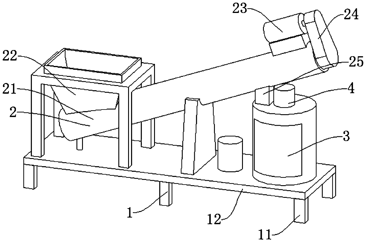
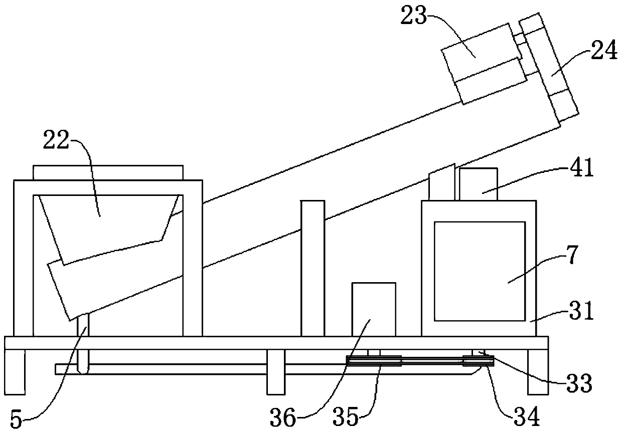
[0040] like Figure 1-Figure 3 , Figure 5-Figure 7 As shown, a chip pressing device of a machining center includes a feeding device 2 arranged above the supporting device 1, a rotating device 3 arranged on one side of the feeding device 2, and a compression device arranged inside the rotating device 3 Institution 4.

[0041]Preferably: the rotating device 3 includes an outer cylinder 31, the outer cylinder 31 is connected with the support device 1, an inner cylinder 32 is arranged inside the outer cylinder 31, a transmission shaft 33 is connected to the lower end of the inner cylinder 32, and a small pulley 34 is connected to the lower end of the transmission shaft 33 One side of the small pulley 34 is provided with a large pulley 35, the large pulley 35 is connected to the output end of the second servo motor 36, and the second servo motor 36 provides rotational power for the inner cylinder 32, so that the iron entering the inner cylinder 32 Chips rotat...

Example Embodiment

[0042] Example 2

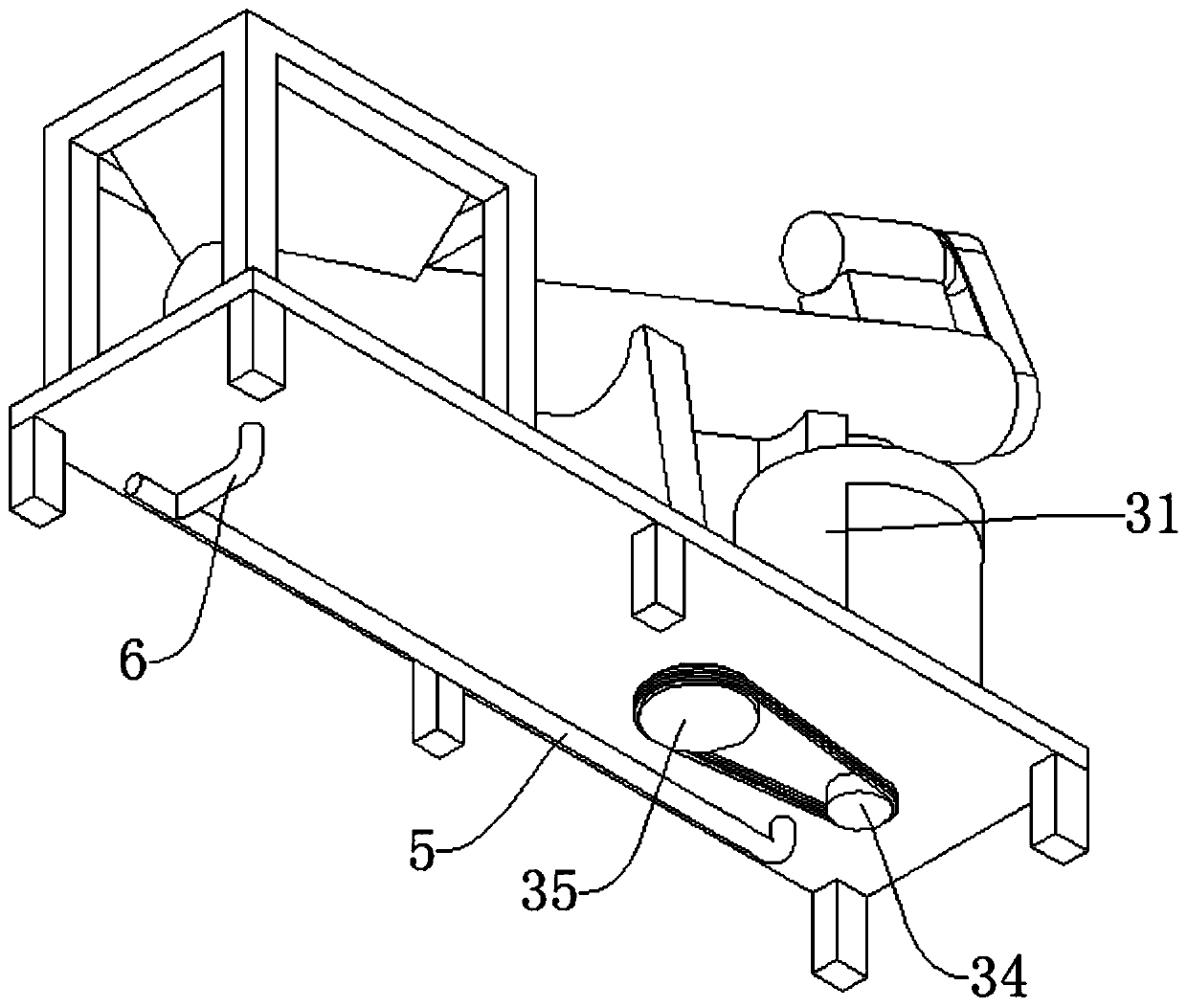
[0043] like Figure 4 , Image 6 , Figure 7 As shown, a chip pressing device of a machining center includes a feeding device 2 arranged above the supporting device 1, a rotating device 3 arranged on one side of the feeding device 2, and a compression device arranged inside the rotating device 3 Institution 4.

[0044] Preferably: the rotating device 3 includes an outer cylinder 31, the outer cylinder 31 is connected to the supporting device 1, the inner cylinder 32 is provided inside the outer cylinder 31, the lower end of the inner cylinder 32 is provided with a rotating groove through which the lower hydraulic cylinder 47 passes, and the lower end of the inner cylinder 32 is connected to Transmission shaft 33 is arranged, and transmission shaft 33 lower ends are connected with small belt pulley 34, and small belt pulley 34 side is provided with large belt pulley 35, and large belt pulley 35 is connected on the second servomotor 36 output ends, passes t...


PUM


Abstract

The invention discloses a scrap iron pressing device of a machining center. The scrap iron pressing device comprises a conveying device arranged above a supporting device and further comprises a rotating device arranged on one side of the conveying device, and a compressing mechanism arranged on the inner side of the rotating device. Cooling liquid is subjected to preliminary separation while theconveying device collects waste, sweeps subjected to preliminary separation enter the rotating device through a discharging hopper and then are subjected to thorough separation again, the separation effect of scrap iron and cooling liquid can be improved, separation is carried out in the seal environment, environment quality is improved, operation space is saved, then, the scrap iron is compressedand recycled through a compression mechanism, direct participation by manual work is avoided, and manual labor intensity is reduced.

Description

technical field [0001] The invention relates to the field of machining, in particular to a pressing device for iron filings in a machining center. Background technique [0002] With the development of processing technology, mechanical processing is gradually carried out by machining centers, which are characterized by high processing efficiency, high precision, and small amount of manual intervention. It contains a lot of coolant (cutting fluid), and the waste chips enter the filter screen of the recovery system along with the coolant to be filtered, and then the iron chips are manually sorted out and piled up on the ground, waiting for personnel to collect and carry them, which not only takes up space and causes serious pollution, Also increased the labor intensity of personnel simultaneously. Contents of the invention [0003] The object of the present invention is to provide a chip pressing device for a machining center in order to solve the above problems. [0004] T...

Claims


Application Information

Patent Timeline
IPC IPC(8): B30B9/32B30B15/00B23Q11/00
CPCB23Q11/00B30B9/32B30B15/00
Inventor 张文星
Owner 广州市永汇自动化设备有限公司
Why Eureka
Try Eureka