
Glass blanking working table body adjusting device for tempered glass production

A technology of adjusting device and tempered glass, which is applied in hoisting device, conveyor control device, transportation and packaging, etc., can solve the problems of backward glass transfer method, unable to transfer glass in stacks, etc., to improve the mechanical conversion efficiency and structure. Simple and efficient

Inactive Publication Date: 2020-02-18
利辛县天鑫玻璃制品有限公司
View PDF9 Cites 1 Cited by
  • Summary
  • Abstract
  • Description
  • Claims
  • Application Information

AI Technical Summary

Problems solved by technology

[0003] The object of the present invention is to provide a glass blanking workbench body adjustment device for tempered glass production, to solve the problem that the existing glass transfer method proposed in the above-mentioned background technology is relatively backward, and the existing handling equipment cannot lift and lift stacks of glasses. Problems with moving

Method used


Image

  • Glass blanking working table body adjusting device for tempered glass production
  • Glass blanking working table body adjusting device for tempered glass production
  • Glass blanking working table body adjusting device for tempered glass production

Examples


Embodiment 1

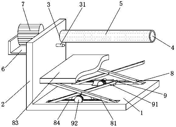
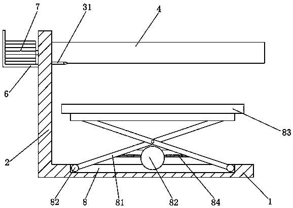
[0024] see Figure 1-3 , this embodiment provides a glass blanking workbench body adjustment device for tempered glass production, including a load-bearing platform 1, one side of the load-bearing platform 1 is integrally provided with a load-bearing plate 2, and the side of the load-bearing plate 2 is provided with a rotary hole 3 The inner wall of the rotating hole 3 is equipped with a freely rotatable roller 4 through the bearing, and the outer wall of the roller 4 is sleeved with a rubber anti-slip sleeve 5, and the side of the load-bearing plate 2 away from the bearing platform 1 is integrally arranged near the rotating hole 3. Fixed mount 6 is arranged, and the inside of fixed mount 6 is fixed with electric motor 7, and the power take-off shaft of electric motor 7 and roller 4 stretch into the center of one end of rotating hole 3 inside and fix, and electric motor 7 is connected with mains by lead.

[0025] The top surface of the load-bearing platform 1 is symmetrically ...

Embodiment 2

[0035] see Figure 1-2 On the basis of Embodiment 1, a further improvement has been made: the top surface of the load-bearing platform 1 is provided with a telescopic frame 81, and the end of the foot of the telescopic frame 81 extends into the inside of the slideway 8, and the bottom end of the telescopic frame 81 is installed There are freely slidable rollers 82, and the bottom side of the rollers 82 is attached to the inner wall of the bottom side of the slideway 8. The sliding friction between the telescopic frame 81 and the slideway 8 can be converted into rolling friction through the rollers 82, which can reduce the expansion and contraction. The resistance experienced by the feet of the frame 81 during relative movement can improve the mechanical conversion efficiency of the servo motor 91 , making the change of the length of the telescopic frame 81 free of frustration and more stable.

[0036] The outer wall of the roller 4 is sleeved with an anti-slip sleeve 5 made of...


PUM


Abstract

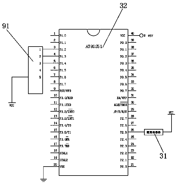
The invention discloses a glass blanking working table body adjusting device for tempered glass production. The glass blanking working table body adjusting device for tempered glass production comprises a bearing platform. A bearing plate is integrally arranged on one side of the bearing platform. A rotating hole is formed in the lateral side of the bearing plate. The interior of the rotating holeis provided with a roller wheel. A power output shaft of a motor is fixed to the center of one end of the roller wheel. The top surface of the bearing table is provided with a slideway. A fixing lugis arranged at the position, close to the slideway, of the top surface of the bearing table. A telescopic frame is arranged on the top surface of the bearing table. The end portion of a bottom foot ofthe telescopic frame extends into the slideway. A fixing plate is fixed to the top end of the telescopic frame. Servo motors are fixed to one side, away from the slideway, of the fixing lug. The twoservo motors are connected in parallel through wires. One side, close to the bearing table, of the bearing plate is fixedly provided with a distance sensor at a position flush with the bottom side ofan anti-sliding sleeve. The output end of the distance sensor is connected with a single chip microcomputer through a wire. Through cooperative use of the devices, the glass carrying efficiency is improved, manpower is liberated, and stacked glass can be transferred.

Description

technical field [0001] The invention relates to the related technical field of tempered glass production equipment, in particular to a body adjustment device of a glass blanking workbench for tempered glass production. Background technique [0002] During the production of tempered glass, ordinary glass needs to be transferred to the conveyor belt and then transferred to the glass tempering mechanism through the conveyor belt. The method used to transfer the glass to the conveyor belt is a more traditional manual handling method. This method is inefficient and high in labor costs. And there are scratches on the palms of the staff, and the glass is broken due to misuse, which is not conducive to the improvement of the production efficiency of tempered glass, and the existing glass blanking device can only carry a single piece of glass, because the table body is fixed and cannot Stacks of glass are transported, so there is an urgent need for a glass blanking workbench body adj...

Claims


Application Information

Patent Timeline
Patent Type & Authority Applications(China)
IPC IPC(8): B65G49/06B65G43/08B65G47/04B66D1/12B66D1/28
CPCB65G43/08B65G47/04B65G49/063B65G2203/042B66D1/12B66D1/28
Inventor 江晋齐
Owner 利辛县天鑫玻璃制品有限公司
Learn More