Microplate sample injection indicating system

A technology of micro-orifice plates and instructions, which is applied in the direction of measuring devices, instruments, scientific instruments, etc., can solve problems such as easy to add wrong holes, increase error rate of sample addition, and reduce test efficiency

Inactive Publication Date: 2020-02-18
NANJING MEDICAL UNIV
View PDF6 Cites 1 Cited by
  • Summary
  • Abstract
  • Description
  • Claims
  • Application Information

AI Technical Summary

Problems solved by technology

[0003] The purpose of the present invention is to provide a microplate sample adding indicator system to solve the problem of manual sample adding or mass sample adding in the above-mentioned background technol

Method used


Image

  • Microplate sample injection indicating system
  • Microplate sample injection indicating system
  • Microplate sample injection indicating system

Examples


Embodiment 1

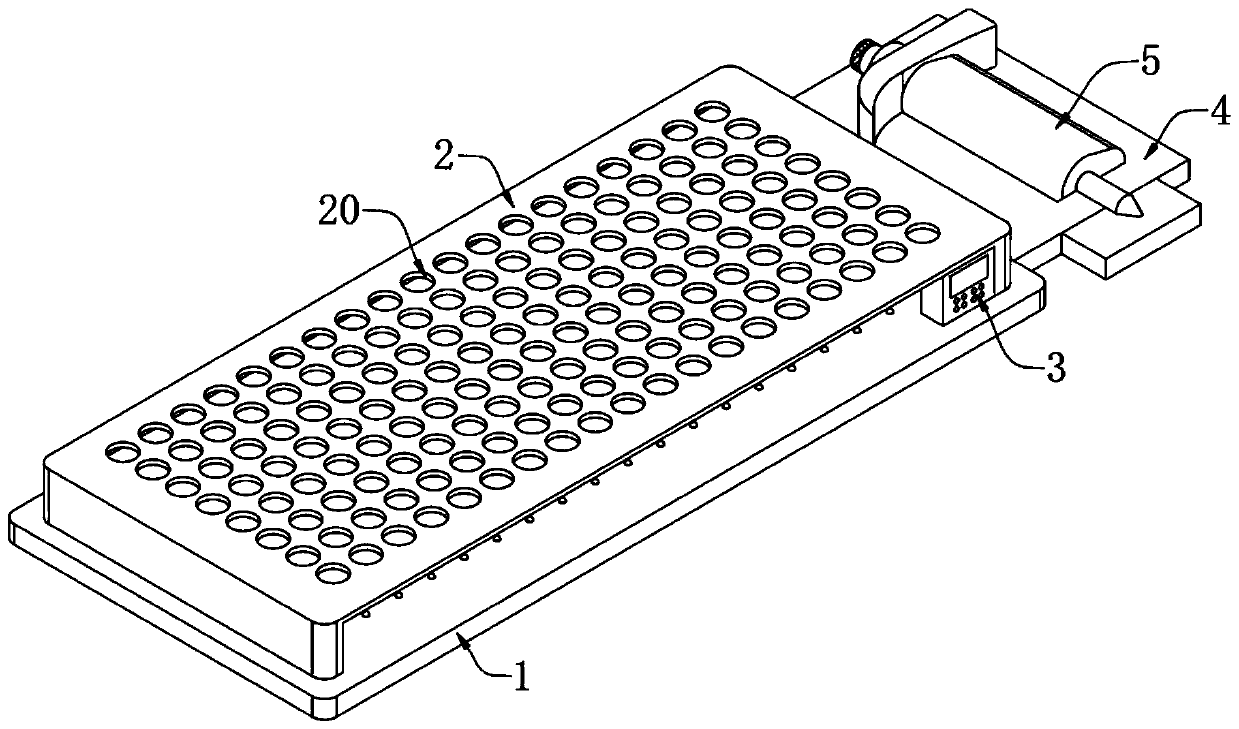
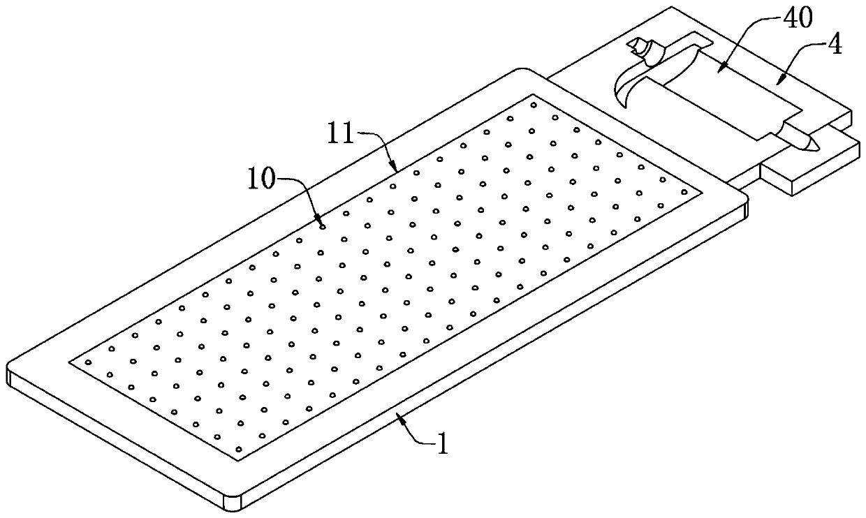
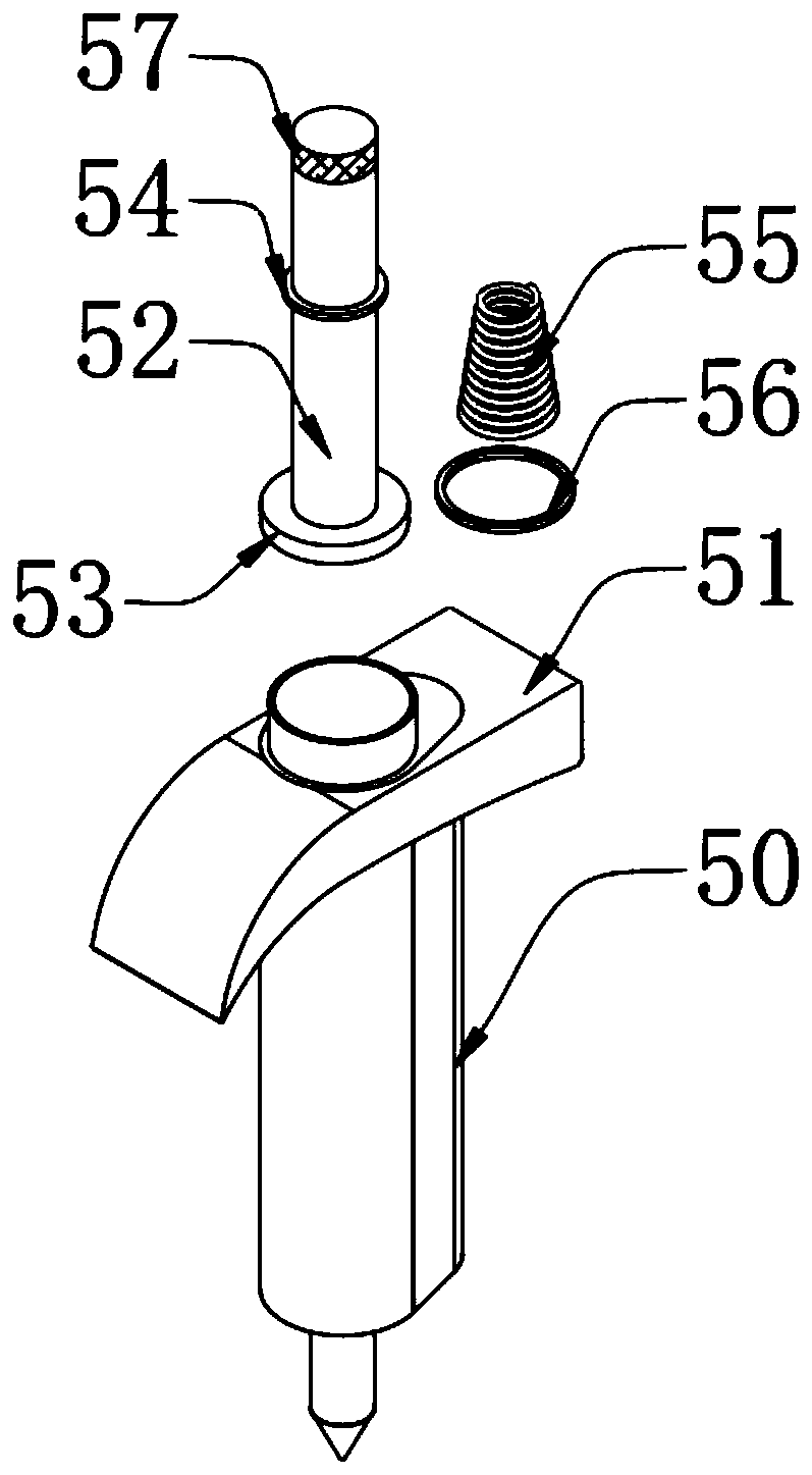
[0101] A microplate loading indicator system, such as Figure 1 to Figure 3 As shown, including the base 1, the top of the base 1 is provided with a placement box 2, the rear side of the base 1 is provided with a placement plate 4, and the upper surface of the placement plate 4 is provided with a gun slot 40, and a sample addition is embedded in the gun slot 40. The gun 5, the sample adding gun 5 comprises a gun barrel 50, the position of the side wall of the gun barrel 50 near the end is provided with an arc-shaped plate 51, an injection rod 52 is installed in the gun barrel 50, and a piston 53 is arranged at the end of the injection rod 52, The injection rod 52 is covered with a spring 55 , and the two ends of the spring 55 are respectively installed with a first fixing ring 54 and a second fixing ring 56 .

[0102] In this embodiment, the arc-shaped plate 51 and the gun barrel 50 are integrally formed to ensure the stability of the connection between the arc-shaped plate 51...

Embodiment 2

[0108] As the second embodiment of the present invention, in order to reduce the error rate and improve the experimental efficiency, the inventor sets the control system, as a preferred embodiment, such as Figure 4 to Figure 10 As shown, there is an induction device 11 installed inside the base 1, a number of indicator lights 10 are arranged at equal intervals on the upper surface of the base 1, a number of placement grooves 20 are arranged at equal intervals on the placement box 2, and a pressure sensor is installed on the top of the side wall of the injection rod 52. 57. A display panel 3 is installed on the right side wall of the storage box 2 close to the rear side, and a control system is installed inside the display panel 3. The control system includes a control module, a key module, a display module, a sensor module and a power module. The module is used to collect pressure signals and palm signals; the button module is used to count the signal data and switch the worki...

Embodiment 3

[0247] As a third embodiment of the present invention, in order to facilitate the monitoring of the sample addition process and improve the accuracy of sample addition, the inventors set up a defined successful sample addition module. As a preferred embodiment, the display panel 3 is also provided with a defined success module. The sample adding module is used for monitoring the sample adding process.

[0248] In this embodiment, the defined successful sample addition module uses an autoregressive model to process and calculate the monitored data signals.

[0249] Further, a copper plate is provided on the upper surface of the base 1, and the copper plate completely covers the placement groove 20, which facilitates subsequent monitoring of the sample addition process and prevents errors in sample addition.

[0250] The introduction of the autoregressive model includes the following poses:

[0251] Posture 1: From the simple pendulum system, let x t is the swing amplitude dur...


PUM


Abstract

The invention relates to the technical field of microplate sample injection equipment, in particular to a microplate sample injection indicating system. The microplate sample injection indicating system comprises a base, wherein a plurality of indicator lamps are arranged on the upper surface of the base at equal intervals; a placement box is arranged above the base; a plurality of placement grooves are formed in the placement box at equal intervals; a placement plate is arranged at the rear side of the base; a gun groove is formed in the upper surface of the placement plate; and a sample injection gun is embedded inside the gun groove. According to the microplate sample injection indicating system, a sensing module is used for collecting a pressure signal and a palm signal, a key module is used for switching signal data counting and working modes, and a control module is used for analyzing and treating the collected signal data, so that the reduction of error rates of sample injectionis facilitated, and the efficiency of experiment is improved; a display module is used for displaying the analyzed and processed signal data; and a power module is used for supplying power to a circuit, so that the normal operation of the circuit is ensured.

Description

technical field [0001] The invention relates to the technical field of microhole plate sample loading equipment, in particular to a microhole plate sample loading indicator system. Background technique [0002] In laboratories such as biochemistry or sanitation and epidemic prevention inspection, it is often necessary to use microplates for detection tests, and then use a microplate reader to detect the absorbance of each well. The transparent plastic plate of the sample has multiple rows of small holes of uniform size, usually with 40 holes, 48 ​​holes, 55 holes or 96 holes of different specifications, and each hole can hold a small amount of solution. The wells are closely arranged, and there are no obvious marks between adjacent wells. Therefore, it is often easy to add wrong wells during manual sample addition or large-scale sample addition, especially when there is no color change in the reagents in the wells. Greatly increased, reducing the test efficiency, in view of...

Claims


Application Information

Patent Timeline
IPC IPC(8): G01N35/10G01N33/543
CPCG01N33/543G01N35/10G01N2035/1027
Inventor 周宇轩朱继峰胡克陈士晟刘政
Owner NANJING MEDICAL UNIV
Why Eureka
Try Eureka