Antenna device with excellent penetrating performance

An antenna device, any position technology, applied in the direction of antenna grounding device, antenna support/installation device, antenna, etc., to achieve the effect of small amplitude, small signal attenuation, and simple structure

Pending Publication Date: 2020-02-18
CHINA RAILWAY ENGINEERING EQUIPMENT GROUP CO LTD
View PDF0 Cites 8 Cited by
  • Summary
  • Abstract
  • Description
  • Claims
  • Application Information

AI Technical Summary

Problems solved by technology

[0005] The invention provides a strong penetrating antenna device buried in reinforced concrete, which is used to solve the problem that the passive tag chip is in a harsh electromagnetic propagation environment (such as when it is built in a concrete structure) and cannot be connected to the outside world through a cable. In the case of the technical problem of communicating with the outside world through the antenna, the technical solution is as follows:

Method used


Image

  • Antenna device with excellent penetrating performance
  • Antenna device with excellent penetrating performance
  • Antenna device with excellent penetrating performance

Examples


Embodiment Construction

[0035] Embodiments of the present invention are described in detail below, examples of which are shown in the drawings, wherein the same or similar reference numerals designate the same or similar elements or elements having the same or similar functions throughout. The embodiments described below by referring to the figures are exemplary only for explaining the present invention and should not be construed as limiting the present invention.

[0036] The following disclosure provides many different implementations or examples for implementing different structures of the present application. To simplify the disclosure of the present application, components and arrangements of specific examples are described below. Of course, they are examples only and are not intended to limit the application. Furthermore, the present application may repeat reference numerals and / or reference letters in various instances, such repetition is for simplicity and clarity and does not in itself ind...


PUM

PropertyMeasurementUnit
thicknessaaaaaaaaaa

Abstract

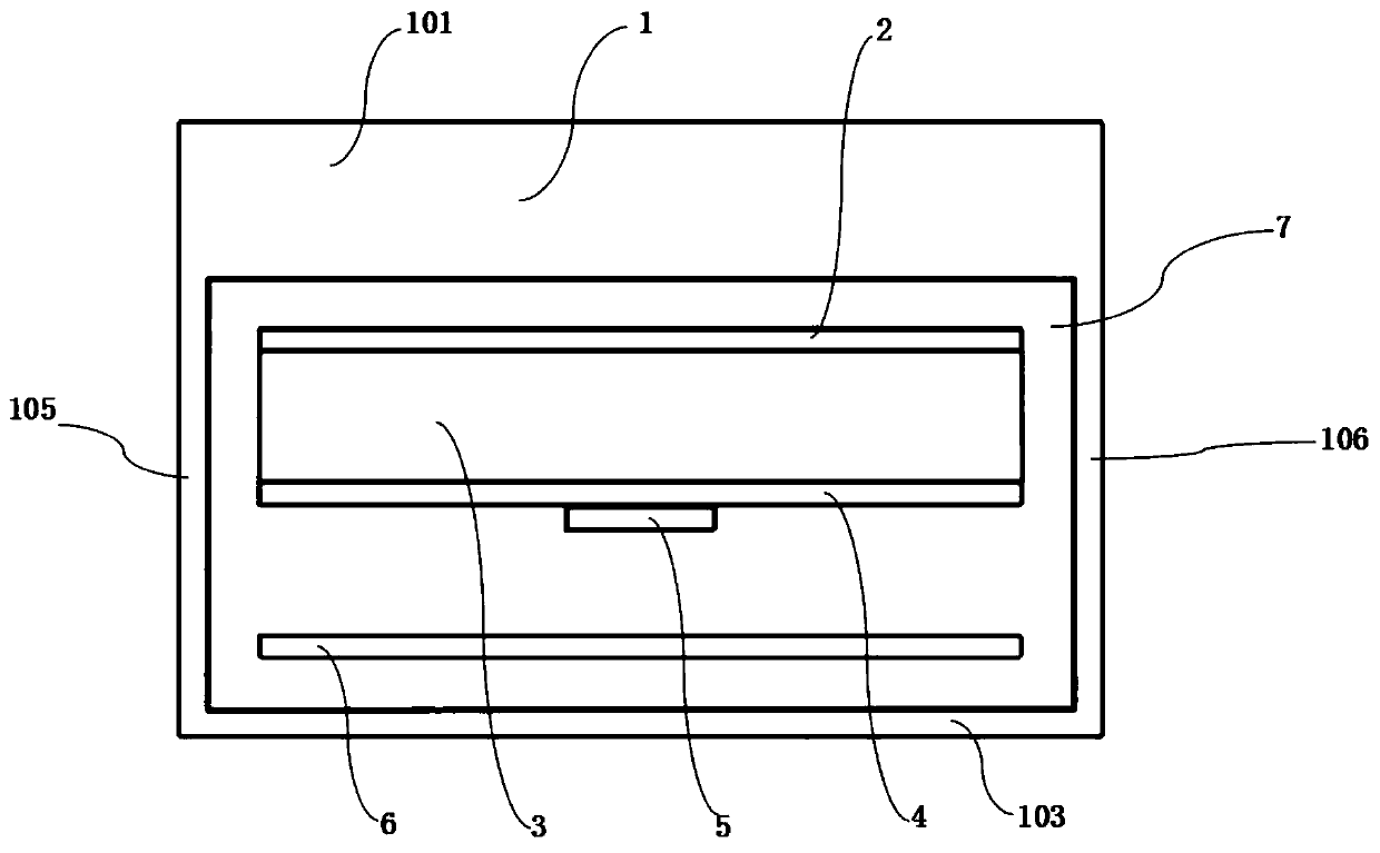
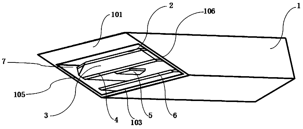
The invention provides an antenna device with excellent penetrating performance. The antenna device includes a first radiator, a second radiator, a third radiator, and a dielectric substrate. The slotof the first radiator is configured to adjust the antenna impedance to achieve an effect of adjusting the resonance frequency. The dielectric substrate with a corresponding dielectric constant is arranged between the first radiator and the second radiator as required. The third radiator is used as a reflection plate, is located below the second radiator and increases the gain in the direction of0-degree angle. A low-dielectric-constant medium with a certain thickness is disposed directly above the first radiator. A feeding point is disposed on the first radiator. The second radiator is grounded. The antenna device has excellent penetrating performance, and can still smoothly transmit energy to the outside when buried in reinforced concrete.

Description

technical field [0001] The invention relates to an antenna electronic device, in particular to a strong penetrating antenna device. Background technique [0002] Most of the antennas are applied in free space or on the surface of objects. Specifically, the antennas of most electronic devices are applied in the air, and some electronic devices are placed on walls, metals, skin surfaces, etc. In short, electronic equipment will be in contact with the air in one direction, which is conducive to the transmission of electromagnetic wave energy. Corresponding research papers on free-space antennas account for the vast majority. Few research papers on antenna design for harsh electromagnetic propagation environments can be retrieved. [0003] The harsh electromagnetic propagation environment has effects such as attenuation, reflection, and scattering on electromagnetic waves. When electronic equipment is placed in such an environment such as reinforced concrete, it is difficult f...

Claims


Application Information

Patent Timeline
Patent Type & Authority Applications(China)
IPC IPC(8): H01Q1/38H01Q1/48H01Q1/50H01Q5/10H01Q5/28H01Q5/307H01Q5/335H01Q5/50H01Q19/10H01Q1/22
CPCH01Q1/22H01Q1/38H01Q1/48H01Q1/50H01Q5/10H01Q5/28H01Q5/307H01Q5/335H01Q5/50H01Q19/106
Inventor 孙恒吴泽庆张国庆黄志勇魏晓龙刘爽
Owner CHINA RAILWAY ENGINEERING EQUIPMENT GROUP CO LTD
Why Eureka
Try Eureka