Low control frequency control method for high switching frequency inverter

A switching frequency and control frequency technology, which is applied in the field of low control frequency control of high switching frequency inverters, can solve the problems of not fully utilizing high switching frequency, current waveform distortion, etc.

Active Publication Date: 2020-02-18
LIYANG RES INST OF SOUTHEAST UNIV +1
View PDF2 Cites 0 Cited by
  • Summary
  • Abstract
  • Description
  • Claims
  • Application Information

AI Technical Summary

Problems solved by technology

[0004] The inventor found through research that the existing inverter control technology with high switching frequency and low control frequency has the following problems: Although the load current ripple can be reduced by relying on high switching frequency, the upda...

Method used


Image

  • Low control frequency control method for high switching frequency inverter
  • Low control frequency control method for high switching frequency inverter
  • Low control frequency control method for high switching frequency inverter

Examples


Embodiment Construction

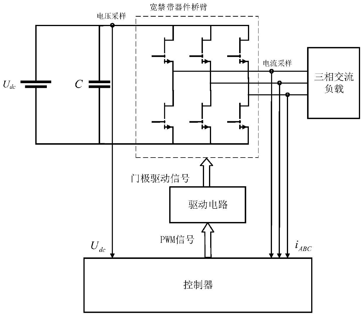
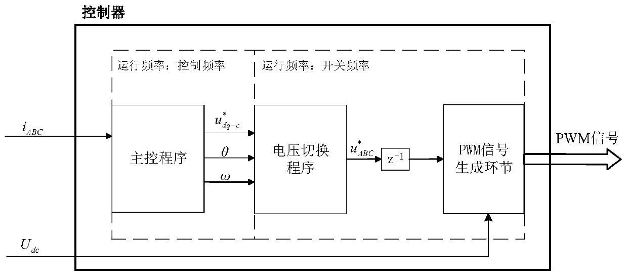
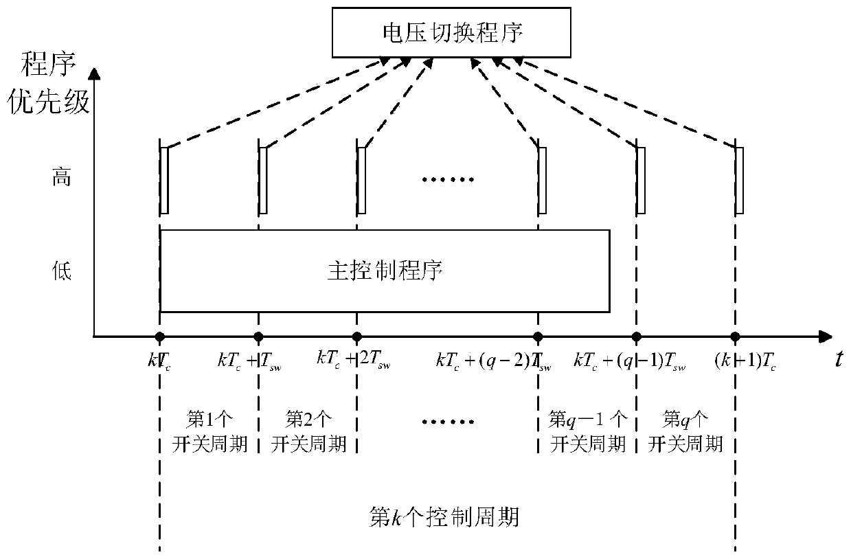
[0066] The present invention proposes a low control frequency control method for high switching frequency inverters, the control method is aimed at the switching frequency f sw higher than the control frequency f c , or a control period T c There are multiple switching periods in T sw In the case of inverter control, the angle of the inverter output voltage vector is changed according to the electrical angular velocity of the dq coordinate system in each switching cycle, and the voltage vector output by the inverter is changed in each switching cycle within a control cycle. In the static coordinate system, the angle that the dq coordinate system turns within one switch cycle. Compared with the prior art, the present invention increases the rotational frequency of the voltage vector, making the motion track of the voltage vector closer to an ideal circle.

[0067] The present invention will be further described below in conjunction with the accompanying drawings.

[0068] A...


PUM


Abstract

The invention discloses a low control frequency control method for a high switching frequency inverter. In each switching period of a control period, the angle of the voltage vector outputted by the high-frequency inverter in a static coordinate system is rotated, the rotation angle is an angle rotated by a dq rotating coordinate system in a switching period, the angle of the output voltage vectoris compensated, and the compensation angle is an angle rotated by the dq rotating coordinate system in a half switching period; and a voltage reference vector of the next switching period in the ABCstatic coordinate system is calculated in each switching period, thereby compensating the delay one-beat characteristic of a PWM wave generator. The control method gives full play to the advantage ofhigh switching frequency, can improve the closeness degree of the output voltage vector of the inverter and the reference voltage vector, improves the sine degree of the output current of the inverter, and remarkably improves the control effect.

Description

technical field [0001] The invention belongs to the field of inverter control, in particular to a low control frequency control method for a high switching frequency inverter. Background technique [0002] Thanks to the development of high-frequency wide bandgap devices-silicon carbide (Silicon Carbide, SiC) devices and gallium nitride (Gallium Nitride, GaN) devices, high-frequency devices can now be used to make high switching frequency inverters (High Switching Frequency Inverter, HSFI) to deal with some occasions that require high frequency drive to improve the control effect, such as using a high switching frequency inverter to control a high frequency permanent magnet synchronous motor (High Frequency Permanent Magnet Synchronous Motor, HFPMSM) can significantly reduce the current ripple. The high switching frequency inverter made of wide bandgap devices can increase the switching frequency to hundreds of kilohertz in small and medium power applications, which is much h...

Claims


Application Information

Patent Timeline
IPC IPC(8): H02P27/12H02P21/13H02P21/26
CPCH02P21/13H02P27/12H02P21/26
Inventor 黄允凯张津栋彭飞姚宇祝子冲
Owner LIYANG RES INST OF SOUTHEAST UNIV
Why Eureka
Try Eureka