
Tire machining forming method

A technology for processing and forming tires, applied in the field of tire processing and forming, can solve the problems of thin wear-resistant rubber layer, adverse effects on vehicle driving safety, and occupation of the distribution space of the wear-resistant rubber layer on the outer wall of the tire.

Active Publication Date: 2020-02-21
CHENG SHIN RUBBER CHINA
View PDF8 Cites 1 Cited by
  • Summary
  • Abstract
  • Description
  • Claims
  • Application Information

AI Technical Summary

Problems solved by technology

[0003] At present, in the molding process implemented in the tire processing process, the blank with relatively flat tread rubber material is usually used for molding processing, but this method causes the rubber material of the tread to flow to the tread ribs after the subsequent vulcanization treatment. Specifically, a large amount of rubber will form deposits inside the junction of the two adjacent surfaces of the tread rib, resulting in uneven distribution of the thickness of the overall internal rubber of the tread rib, resulting in ground contact shape and pressure during subsequent tire rolling work. Uneven distribution will seriously affect the running performance of the tire; and the above-mentioned local silted rubber material will produce a bulge at the junction of the two adjacent surfaces of the tread rib, resulting in the occupation of the distribution space of the wear-resistant rubber layer on the outer wall of the tire. As a result, the wear-resistant rubber layer on the outer wall of the tire is relatively thin, which is prone to premature wear during subsequent use and causes the rubber inside the tire to be exposed, which seriously restricts the service life and performance of the tire, and is detrimental to the safety of the vehicle. influences

Method used


Image

  • Tire machining forming method
  • Tire machining forming method
  • Tire machining forming method

Examples


Embodiment Construction

[0022] The core of the present invention is to provide a tire processing and molding method, which can effectively optimize the rubber material distribution structure at the tread ribs of the tire, avoid local rubber material accumulation and local rubber material protrusions, and improve tire performance.

[0023] In order to enable those skilled in the art to better understand the solution of the present invention, the present invention will be further described in detail below in conjunction with the accompanying drawings and specific embodiments.

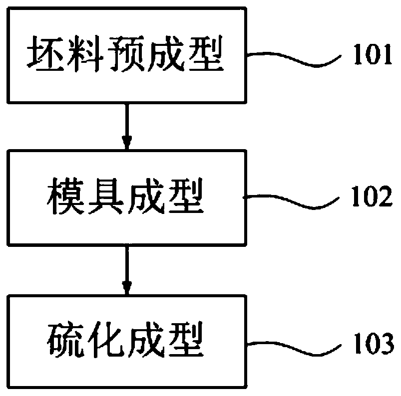
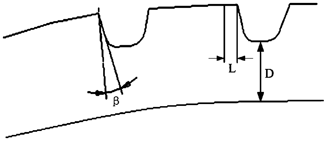
[0024] Please refer to figure 1 and figure 2 , figure 1 A flow chart of the tire processing and molding method provided for a specific embodiment of the present invention; figure 2 It is a schematic cross-sectional structure diagram of a blank provided by a specific embodiment of the present invention.

[0025] In a specific embodiment of the present invention, the tire processing and molding method provided by the present ...


PUM


Abstract

The invention discloses a tire machining forming method. The tire machining forming method comprises the steps of blank preforming, mold forming, vulcanization forming and the like in sequence. A plurality of preforming gutters and preforming protrusions are pre-machined in a rubber blank which is not subjected to mold machining so that the rubber blank can be matched with structures in a mold cavity and corresponding tread pattern grooves and tread pattern strips can be machined, especially, through the blank preforming procedure, rubber can be orderly guided and uniformly distributed, accordingly, the phenomena that due to follow-up mold machining and related forming technology implementation, possibly, the rubber flows and is accumulated on edge parts of the tread pattern strips are effectively avoided, and thus, the phenomenon that the rubber of the tread pattern strips partially protrudes is further avoided; and accordingly, the rubber distribution structure at the tread pattern strips of a tire subjected to machining forming is effectively optimized, the performance of the tire is improved remarkably, the service life of the tire is prolonged remarkably, and the whole vehicleperformance is optimized correspondingly.

Description

technical field [0001] The invention relates to the technical field of tire design, processing and manufacturing, in particular to a tire processing and molding method. Background technique [0002] Tires are the only contact parts between the vehicle and the ground during daily driving. Therefore, the performance of the tires directly affects the driving performance of the vehicle. Among them, whether the stress distribution of the tire under the ground contact state is uniform is one of the extremely important performance indicators, especially for the acronym for NSB (Non-Skid Base, that is, the thickness of the rubber under the groove, which refers to the thickness of the tire under the main groove of the tread pattern. For thinner tires, it should be ensured that the rubber material layout design of each tire rib in contact with the ground is uniform and reasonable, so as to ensure the corresponding tire performance. [0003] At present, in the molding process implemen...

Claims


Application Information

Patent Timeline
Patent Type & Authority Applications(China)
IPC IPC(8): B29D30/08B29D30/06
CPCB29D30/0601B29D30/08
Inventor 张吉荣焦保民方晓云
Owner CHENG SHIN RUBBER CHINA
Learn More