Intelligent pile hole inner muck suction machine and pile hole muck automatic suction method

A soil suction machine and muck technology, which is applied to sheet pile wall, construction, infrastructure engineering, etc., can solve the problems of caking or sticking on the inner wall of the collecting device, difficult to control the falling speed, and less soil mass.

Pending Publication Date: 2020-02-21
甘肃中建市政工程勘察设计研究院有限公司 +1
View PDF0 Cites 1 Cited by
  • Summary
  • Abstract
  • Description
  • Claims
  • Application Information

AI Technical Summary

Problems solved by technology

However, because the pile hole is too deep, there is no soil suction machine for sucking the soil at the bottom of the pile hole. Only a rotary drilling rig can be used for drilling, but the rotary drilling rig can take out very little soil each time. It takes one day to drill the soil in a pile hole. There are many pile holes in a construction site. It may take more than ten days or even a month to drill the soil at the bottom of each pile hole. Seriously. Affected the progress of the construction
At the same time, due to the different soil quality in different places, the soil viscosity and humidity in some places are slightly higher, so the soil sucked up from the bottom of the pile hole is easy to agglomerate in the collection device or stick to the inner wall of the collection device, which needs to be removed manually. In addition, when the soil falls from the collection device to the trolley, the falling speed is not easy to control, resulting in some trolleys being too full, and the soil spills out; some trolleys are loaded too little, and the work efficiency is low.

Method used


Image

  • Intelligent pile hole inner muck suction machine and pile hole muck automatic suction method
  • Intelligent pile hole inner muck suction machine and pile hole muck automatic suction method
  • Intelligent pile hole inner muck suction machine and pile hole muck automatic suction method

Examples


Embodiment 1

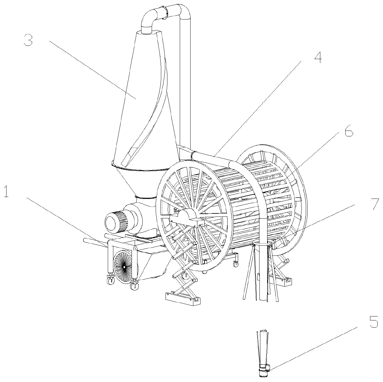
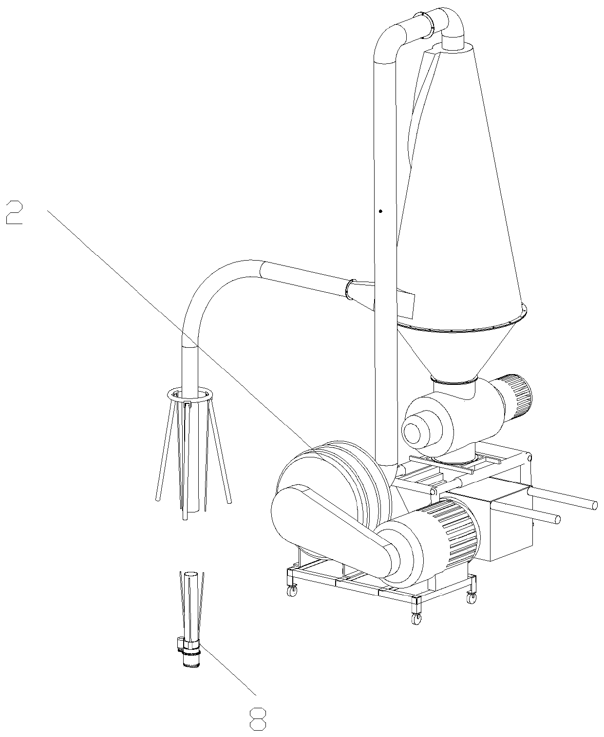
[0069] see figure 1 and 2 , the pile hole muck soil suction machine of this embodiment includes a chassis 1, a blower fan 2, a suction separation device 3, a suction pipe 4, a suction unit 5, a pipeline retractable mechanism 6, a suction moving mechanism 7, a controller 9, a general Control platform 10 and imaging mechanism 8; Wherein,

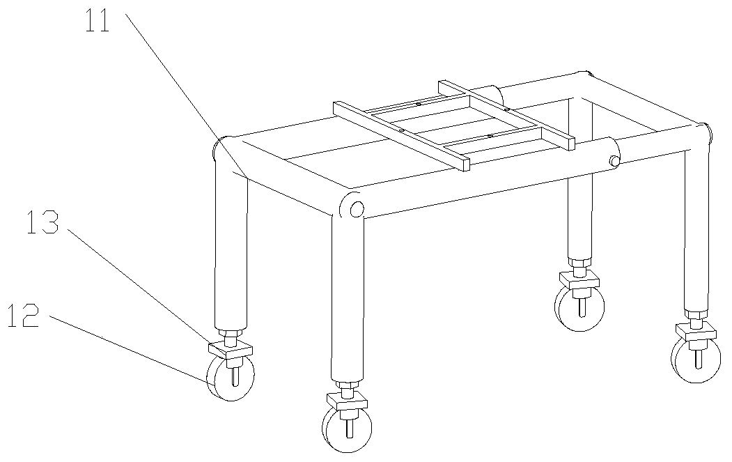
[0070] The chassis 1 provides an installation platform for the suction separation device 3 and the fan 2; as image 3 As shown, the underframe 1 includes a frame body 11, running wheels 12 and a locking mechanism 13. The four running wheels 12 are installed on the four corners of the bottom of the frame body 11 to drive the frame body 11 to slide. A locking mechanism 13 is installed at the wheel 12, and the running wheel 12 is locked and fixed by the locking mechanism 13. The frame body 11 is a telescopic frame body 11 composed of beams, longitudinal beams and supporting legs, that is, the beams, longitudinal beams and supporting legs are a...

Embodiment 2

[0096] The difference between the structure of the pile hole dreg soil suction machine of the present embodiment and embodiment 1 is:

[0097] The vortex separation cylinder 31 of the suction separation device 3 is a conical cylinder structure with a cone angle of 45° and a height of 3m; The direction of the air flow in the inner cavity of the vortex separation cylinder 31 is opposite to that of the vortex separator, and the helix angle of the muck collection tank 32 is 30°, and the pitch is 6m. The discharge valve 34 of the present embodiment is fixed on the chassis 1, and five rotating blades 344 are arranged in the inner cavity of the valve body 341. The rotating blades 344 are rectangular plates and are evenly distributed along the radial direction of the rotating shaft 342. Take the rotating shaft 342 as the central shaft 561 to rotate, the rotating shaft 342 is horizontally arranged, and is connected to the output shaft of the unloading driving motor 343 through a bearin...

Embodiment 3

[0116] The difference between the structure of the pile hole dreg soil suction machine of the present embodiment and embodiment 1 is:

[0117] In the present embodiment, the free end side wall of the suction pipe 4 is processed with a rotating through groove.

[0118] The vortex separation cylinder 31 of the suction separation device 3 is a conical cylinder structure with a cone angle of 45° and a height of 3m; Contrary to the direction of the air flow in the inner cavity of the vortex separation cylinder 31, the muck collection groove 32 protrudes outward along the wall of the vortex separation cylinder 31 and the notch is opened towards the central axis of the vortex separation cylinder 31, and runs along the wall of the vortex separation cylinder 31 from top to bottom Inclined setting enables the collected muck to slide and move from top to bottom. The inclination angle of the muck collecting tank 32 is 30°~60°, preferably 30~45°.

[0119] The suction unit 5 includes a fi...


PUM


Abstract

The invention belongs to the technical field of engineering machinery, and particularly relates to an intelligent pile hole inner muck suction machine and a pile hole muck automatic suction method. The intelligent pile hole inner muck suction machine comprises a chassis, a fan, a suction separation device, a suction pipe, a suction unit, a controller, a master control platform and an imaging mechanism; the suction unit is arranged at the tail end of the suction pipe, the suction separation device is arranged above the chassis, the imaging mechanism is arranged at the tail end of the suction pipe, the suction unit and the imaging mechanism are electrically connected with the controller, and the controller and the imaging mechanism are electrically connected with the master control platformor are in wireless communication with the master control platform; According to the muck suction machine, the problem that mucks in the bottom of pile holes are difficult to clean is solved, the large-block mucks are subjected to rotary cutting, scattering and separation by using the suction unit, and the scattered mucks are sucked into the suction separation device to complete gas and dust separation as the airflow enters the suction separation device through the negative pressure suction principle.

Description

technical field [0001] The invention belongs to the technical field of engineering machinery, and in particular relates to an intelligent suction machine for muck in pile holes and an automatic suction method for muck in pile holes. Background technique [0002] For large-scale buildings, such as bridges, high-rise buildings, etc., the first task in the construction process is to drill pile holes, and then lower reinforcement cages in the pile holes. The height of the reinforcement cages is in one-to-one correspondence with the depth of the pile holes. However, during the on-site construction, the construction personnel found that the reinforcement cage would often be 2 to 5 meters above the ground level after being lowered, and could not be completely lowered to the bottom of the pile hole. If the cage is cut off, or the construction is carried out directly, the actual strength of the building will not meet the design strength required, which may lead to serious safety prob...

Claims


Application Information

Patent Timeline
Patent Type & Authority Applications(China)
IPC IPC(8): E02D13/08
CPCE02D13/08
Inventor 孙志虎李伟利郭志元刘博怀薛彦琪李征
Owner 甘肃中建市政工程勘察设计研究院有限公司
Why Eureka
Try Eureka