A turbine engine hot end combustion lubricating oil pipeline structure
A turbine engine and lubricating oil technology, which is applied in the direction of engine components, machines/engines, mechanical equipment, etc., can solve the problems of not reducing lubricating oil coking, bearing cooling effect, improving engine thermal efficiency, and reducing lubricating oil temperature, etc. Achieve good atomization combustion effect, reduce the probability of coking, and improve the effect of cooling effect
- Summary
- Abstract
- Description
- Claims
- Application Information
AI Technical Summary
Problems solved by technology
Method used
Image
Examples
Embodiment 1
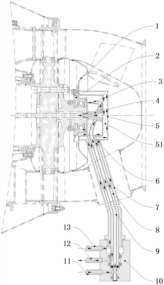
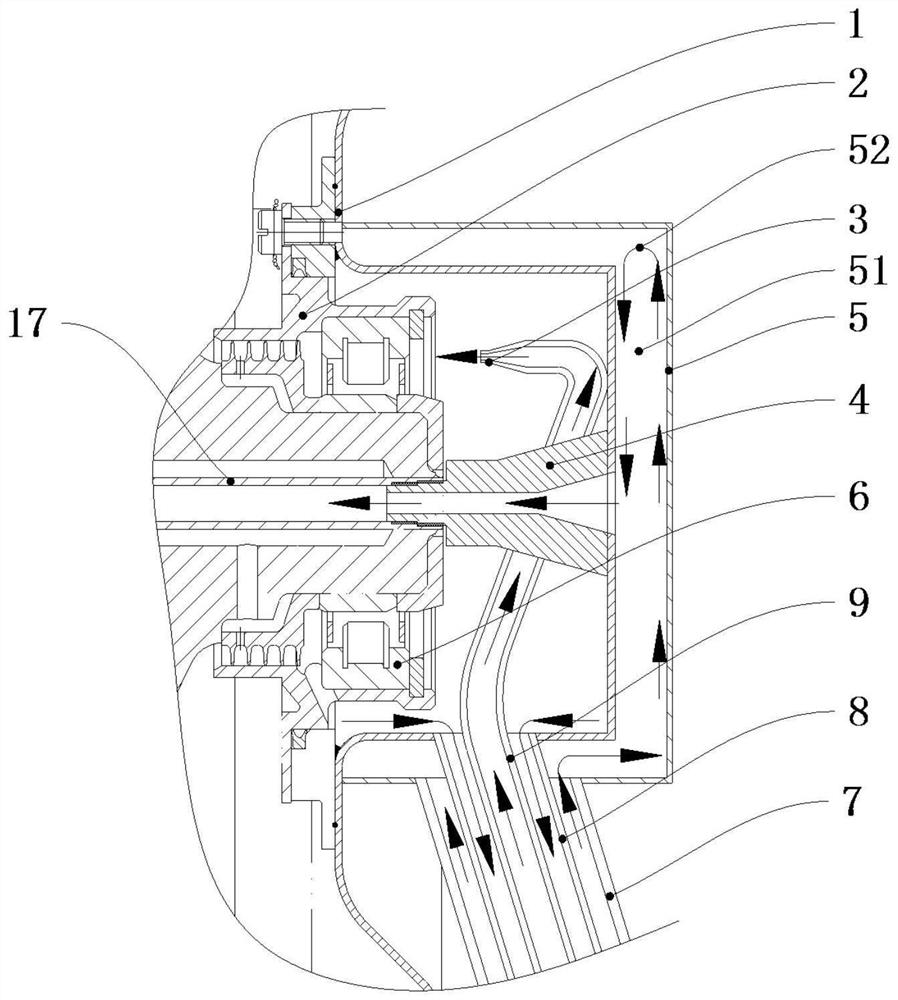
[0031]Such as Figure 1-5 As shown, a turbine engine hot end combustion oil pipeline structure includes a bearing 6, a bearing seat 2 is installed on the bearing 6, a lubricating oil return chamber housing 1 is installed on the bearing housing 2, and the lubricating oil return chamber housing 1 is wrapped with a fuel preheating chamber casing 5, and a fuel preheating chamber 51 is formed between the fuel preheating chamber casing 5 and the lubricating oil return chamber casing 1; it also includes nesting from the outside to the inside and leaving a gap between them One end of the fuel inlet pipe 7 communicates with the fuel preheating chamber 51, the fuel preheating chamber 51 communicates with the oil supply pipe 17, and the lubricating oil return pipe 8 One end communicates with the inside of the lubricating oil return chamber housing 1 , and one end of the lubricating oil inlet pipe 9 is located inside the lubricating oil return chamber housing 1 and opposite to the upper p...
Embodiment 2
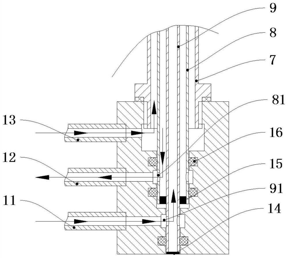
[0035] Such as Figure 1-5 As shown, on the basis of the above embodiments, this embodiment provides a preferred mechanism for connecting the fuel oil inlet pipe, the lubricating oil return pipe and the other end of the lubricating oil inlet pipe. That is, the other ends of the fuel inlet pipe 7, the lubricating oil return pipe 8 and the lubricating oil inlet pipe 9 are connected to the same pipe adapter 10, and the pipe adapter 10 is sequentially installed with a fuel oil inlet joint 13 and a lubricating oil outlet joint 12 , oil inlet joint 11, fuel oil inlet joint 13, oil outlet joint 12, oil inlet joint 11 are communicated with fuel oil inlet pipe 7, oil return pipe 8 and oil inlet pipe 9 successively.
[0036] Preferably, the middle part of the pipeline adapter 10 is sequentially provided with a fuel pipe connection hole 107, a lubricating oil return pipe connection hole 108 and a lubricating oil inlet pipe connection hole 109 from top to bottom, the fuel oil inlet pipe 7...
PUM
 Abstract
Description
Claims
Application Information
 - R&D
- Intellectual Property
- Life Sciences
- Materials
- Tech Scout
- Unparalleled Data Quality
- Higher Quality Content
- 60% Fewer Hallucinations
Browse by: Latest US Patents, China's latest patents, Technical Efficacy Thesaurus, Application Domain, Technology Topic, Popular Technical Reports.
© 2025 PatSnap. All rights reserved.Legal|Privacy policy|Modern Slavery Act Transparency Statement|Sitemap|About US| Contact US: help@patsnap.com


