Stress-insensitive MEMS capacitive Z-axis accelerometer

An accelerometer and stress-response technology, applied in the direction of using inertial force for acceleration measurement, measurement of acceleration, velocity/acceleration/shock measurement, etc. Stress, deformation influence inhibition and other issues, to achieve the effect of increasing manufacturing difficulty, good linearity, and small temperature drift

Pending Publication Date: 2020-02-21
SUZHOU R&D CENT OF NO 214 RES INST OF CHINA NORTH IND GRP
View PDF18 Cites 13 Cited by
  • Summary
  • Abstract
  • Description
  • Claims
  • Application Information

AI Technical Summary

Problems solved by technology

In the two designs, the mass block anchor point and the fixed tooth anchor point are designed in a decentralized arrangement. This design cannot well adapt to the substrate deformation caused by external stress and temperature changes, resulting in output drift caused by changes in sensitive capacitance.
[0007] At present, there are two main means to reduce or suppress the impact of external stress and temperature changes on the drift of MEMS capacitive accelerometers: one is stress relief or isolation design, such as ZL201410306360.4 introduces a method of making bumps based on silicon-silicon bonding For the stress isolation structure of the support layer, CN201510473172 introduces a monolithically integrated embedded stress isolation structure. On the one hand, the above stress isolation structure increases the difficulty of chip fabrication or packaging, and cannot affect the stress and deformation from the source of the sensitive unit. Inhibition; the second is to design a sensitive unit that is not sensitive to stress. CN201510114611.3 introduces a MEMS chip that is not sensitive to packaging stress. By suspending the lower electrode plate of the flat capacitor at a single point, the lower electrode plate is not subject to substrate deformation. The impact of this solution involves multiple silicon-silicon bonding processes, making it difficult to manufacture

Method used


Image

  • Stress-insensitive MEMS capacitive Z-axis accelerometer
  • Stress-insensitive MEMS capacitive Z-axis accelerometer
  • Stress-insensitive MEMS capacitive Z-axis accelerometer

Examples


Embodiment Construction

[0039] The present invention will be further described below in conjunction with the accompanying drawings. The following examples are only used to illustrate the technical solution of the present invention more clearly, but not to limit the protection scope of the present invention.

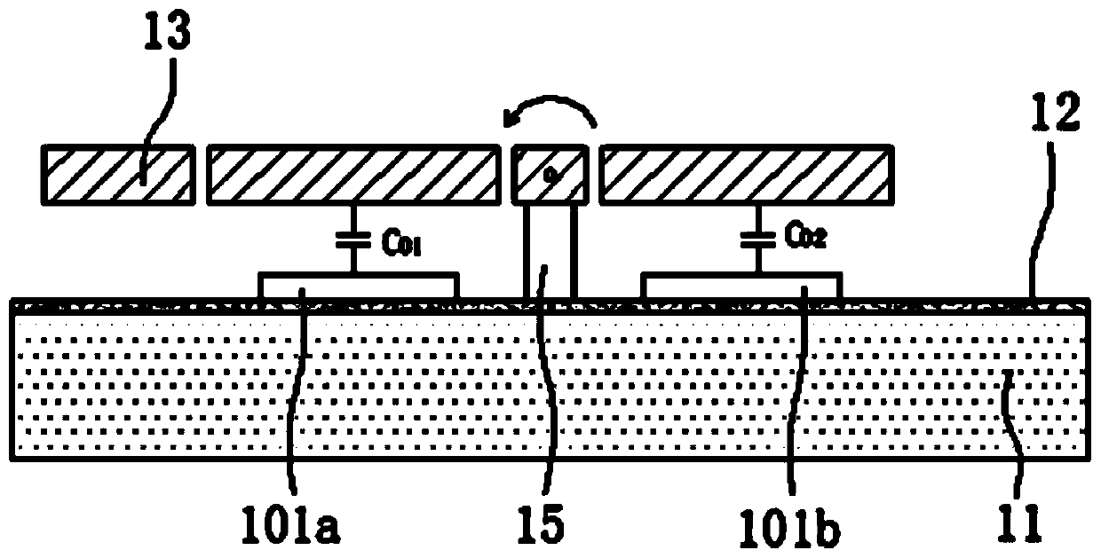
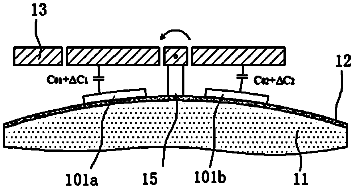
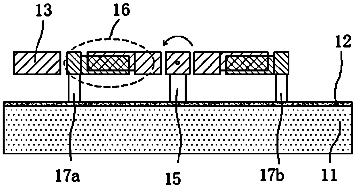
[0040] The MEMS capacitive Z-axis accelerometer insensitive to stress of the present invention, the overall schematic diagram is as Figure 3A and Figure 3B As shown, the sensitive unit 1 includes a substrate 11 , a movable mass 13 , a fixed comb 16 b , a fixed tooth anchor 17 , a support beam 14 and a central anchor 15 . The movable mass 13 is suspended from the central anchor point 15 via two support beams 14, and the central anchor point 15 is fixed on the substrate 11. The movable mass 13 uses the support beam 14 as the torsion axis, and has poor mass on both sides. The fixed comb 16b includes a comb arm 16c, which is fixed to the substrate via the anchor point 17 of the fixed tooth. The ...


PUM


Abstract

The invention discloses a stress-insensitive MEMS capacitive Z-axis accelerometer. Each sensitive unit comprises a substrate, movable mass blocks, fixed comb teeth, fixed tooth anchor points, two supporting beams and a central anchor point, wherein the movable mass blocks are suspended at the central anchor point through the two supporting beams, and the central anchor point is fixed to the substrate; the supporting beams serve as twisting shafts of the movable mass blocks, and the movable mass blocks distributed at the two sides of the supporting beams have a mass difference; the fixed toothanchor points symmetric around the supporting beams are arranged on the positions, at the two sides of the central anchor point, of the substrate, and the fixed comb teeth are arranged on the fixed tooth anchor points; and each movable mass block is provided with movable comb teeth in the direction facing the fixed tooth anchor points, the movable comb teeth are inserted between the fixed comb teeth in a matched mode, and a group of comb tooth capacitors is formed at each of the two sides of the central anchor point. The stress-insensitive MEMS capacitive Z-axis accelerometer has the advantages that linearity is good, temperature drift is small, long-term stability is good, and manufacturing difficulty is not remarkably increased.

Description

technical field [0001] The invention relates to the technical field of silicon micromechanical sensors, in particular to a MEMS capacitive Z-axis accelerometer which is not sensitive to stress. Background technique [0002] As an important application field of MEMS technology, silicon micro-accelerometer has been widely used in various fields of inertial measurement due to its advantages of low cost, small size, low power consumption, easy integration, and high reliability. Capacitive silicon micro-accelerometers have become one of the most developed and widely used inertial devices due to their excellent characteristics such as simple manufacturing process, good repeatability, and low drift. With the development of technology, the performance requirements of MEMS accelerometers are getting higher and higher, and the influence of external stress and temperature on the performance of MEMS capacitive accelerometers is particularly significant. [0003] The basic working princ...

Claims


Application Information

Patent Timeline
Patent Type & Authority Applications(China)
IPC IPC(8): G01P15/125G01P15/08
CPCG01P15/125G01P15/0802G01P2015/0831
Inventor 周铭鞠莉娜黄艳辉白小丽
Owner SUZHOU R&D CENT OF NO 214 RES INST OF CHINA NORTH IND GRP
Why Eureka
Try Eureka