Battery cover plate
A battery cover and cover technology, applied in the direction of battery cover/end cover, battery pack components, battery box/jacket, etc., can solve the problems of high maintenance cost and short circuit of welding ring, and achieve low maintenance cost and easy maintenance. Short circuit, good insulation effect
- Summary
- Abstract
- Description
- Claims
- Application Information
AI Technical Summary
Problems solved by technology
Method used
Image

Examples
Embodiment 1
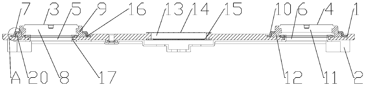
[0040] Embodiment 1: The manufacturing process of the positive electrode assembly 3 and the negative electrode assembly 4 is: the positive pole 8 is stamped or machined, the negative pole 11 is stamped or machined—welding ring one 7 and welding ring two 10 are stamped and made— The positive pole 8 is integrated with the injection part 1 9 by injection molding, and the negative pole pole 11 is integrated with the injection part 2 12 through injection molding. 12 on. The outer edge of the welding ring one 7 is fixedly connected with the side wall of the corresponding U-shaped groove 16 on the cover body 1 by laser welding; The side walls of the U-shaped groove 16 are fixedly connected. In this process, only the positive pole 8 and the negative pole 11 are assembled after injection molding alone, the manufacturing process is simple, and there is no short circuit caused by deformation of the welding ring due to excessive pressure during injection.
Embodiment 2
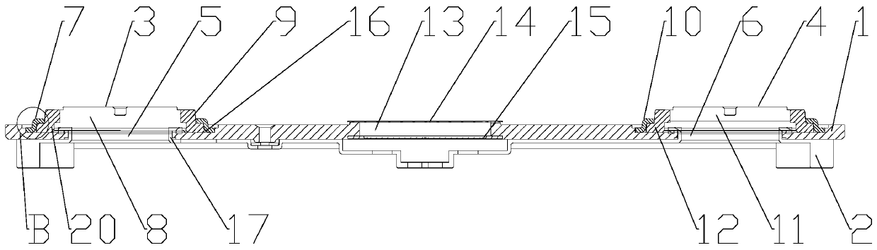
[0041] Embodiment 2: The manufacturing process of the positive electrode assembly 3 and the negative electrode assembly 4 is: the positive pole 8 is punched or machined, the negative pole 11 is punched or machined—welding ring one 7 and welding ring two 10 are stamped and manufactured— Manufacture injection part one 9 and injection part two 12 - assembly of positive pole 8 and assembly of negative pole 11. When the positive electrode assembly 3 is assembled, the positive electrode pole 8 is installed in the injection-molded part-9, the injection-molded part-9 is installed in the welding ring-7, and the outer edge of the welding ring-7 is laser welded with the corresponding U on the cover plate body 1. The side walls of the groove 16 are fixedly connected; when the negative electrode assembly 4 is assembled, the negative electrode pole 11 is installed in the second injection part 12, the second injection part 12 is installed in the second welding ring 10, and the outer edge of t...
Embodiment 3
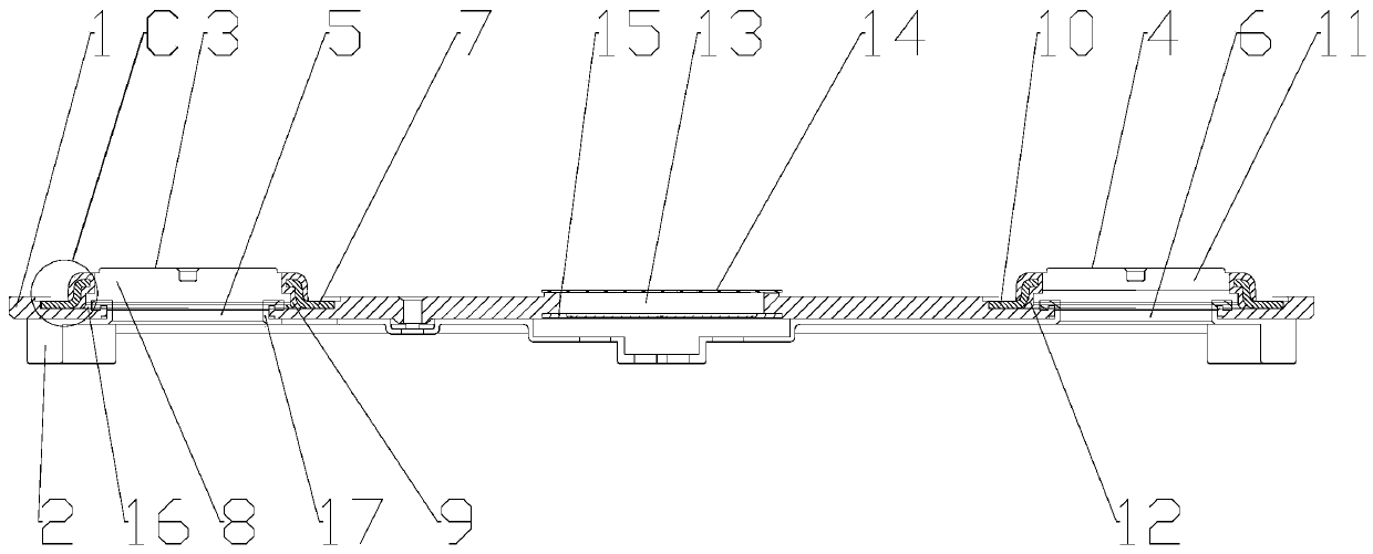
[0042] Embodiment 3: The manufacturing process of the positive electrode assembly 3 and the negative electrode assembly 4 is: the positive pole 8 is punched or machined, the negative pole 11 is punched or machined—welding ring one 7 and welding ring two 10—welding ring One 7 is nested in injection part one 9 by injection molding, welding ring two 10 is nested in injection part two 12 by injection molding—positive pole 8 is installed in injection part one 9, and negative pole 11 is installed in injection part two within 12. The outer edge of the welding ring one 7 is fixedly connected with the side wall of the corresponding U-shaped groove 16 on the cover body 1 by laser welding; The side walls of the U-shaped groove 16 are fixedly connected. This process adopts the welding ring one 7 and the welding ring two 10 to be assembled after plastic embedding, the manufacturing process is simple, and it is easy to realize fully automatic manufacturing.
PUM
 Abstract
Description
Claims
Application Information
 - Generate Ideas
- Intellectual Property
- Life Sciences
- Materials
- Tech Scout
- Unparalleled Data Quality
- Higher Quality Content
- 60% Fewer Hallucinations
Browse by: Latest US Patents, China's latest patents, Technical Efficacy Thesaurus, Application Domain, Technology Topic, Popular Technical Reports.
© 2025 PatSnap. All rights reserved.Legal|Privacy policy|Modern Slavery Act Transparency Statement|Sitemap|About US| Contact US: help@patsnap.com