Cross-coupling dielectric waveguide filter

A cross-coupling, dielectric waveguide technology, applied in the field of communications, can solve problems such as low squareness and inability to change the cross-zero structure, and achieve the effect of reducing impact, facilitating miniaturization and consistency, and improving out-of-band suppression

Active Publication Date: 2020-02-21
CHINA ELECTRONICS TECH GRP NO 26 RES INST
View PDF9 Cites 9 Cited by
  • Summary
  • Abstract
  • Description
  • Claims
  • Application Information

AI Technical Summary

Problems solved by technology

[0004] However, due to the impact of its structure, the dielectric waveguide cannot flexibly change the cross-zero structure like the traditional metal cavity; Chinese patent CN110277612A proposes a dielectric waveguide filter with symmetrical cross-coupling zeros; The first blind hole and the second blind hole that are symmetrical to the dielectric resonance center can realize cross-coupling zero point and improve out-of-band suppression, thereby reducing the impact on other communication frequency bands. However, it can be seen in Figure 9 of the patent that, The squareness of this scheme is not high, and other effects need to be further improved; therefore, in order to improve the frequency selection filtering performance of the base station, it is an urgent problem to be solved to achieve low loss, high squareness of the filter and improve the out-of-band rejection of the filter

Method used


Image

  • Cross-coupling dielectric waveguide filter
  • Cross-coupling dielectric waveguide filter
  • Cross-coupling dielectric waveguide filter

Examples


Embodiment 1

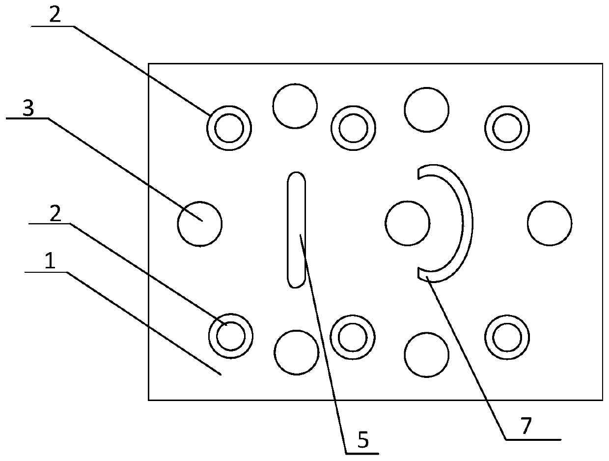
[0029] like figure 1 As shown, this embodiment provides a 6th-order 4-notch cross-coupling dielectric waveguide filter, which corresponds to 3 groups of resonant holes, and specifically includes a ceramic dielectric body 1, and the outer side of the ceramic dielectric body is metallized to form a metal shield There are 3 groups of resonant holes on one side surface of the ceramic dielectric body, the two resonant blind holes in the vertical direction in the figure are a group, and from left to right are the first group, the second group and the third group. ; Each group of resonant holes includes two symmetrically arranged resonant blind holes 2; between each group of resonant holes is a through-slot penetrating the ceramic dielectric body, that is, two through-slots, one of which is an arc-shaped through-slot 7. The other through slot is an elongated through slot 5; several resonant cavities are separated by the through slot; a plurality of coupling blind holes 3 with adjusta...

Embodiment 2

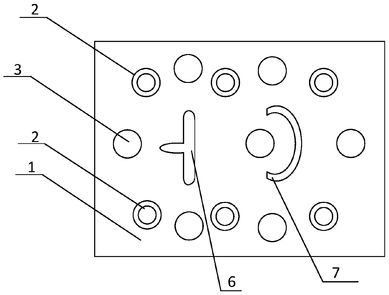
[0031] like figure 2 As shown, this embodiment provides another 6th-order 4-notch cross-coupling dielectric waveguide filter, which corresponds to 3 groups of resonant holes, specifically including a ceramic dielectric body 1, and the outside of the ceramic dielectric body is metallized to form a metal Shielding layer; 3 groups of resonant holes are arranged on one side surface of the ceramic dielectric body. The two resonant blind holes in the vertical direction in the figure are a group, and from left to right are the first group, the second group and the third group. Each group of resonant holes includes two symmetrically arranged resonant blind holes 2; between each group of resonant holes, there is a through slot through the ceramic dielectric body, that is, two through slots, one of which is an arc-shaped through slot. Slot 7, the other through slot is a T-shaped through slot 6; several resonant cavities are separated by the through slot; a plurality of coupling blind h...

Embodiment 3

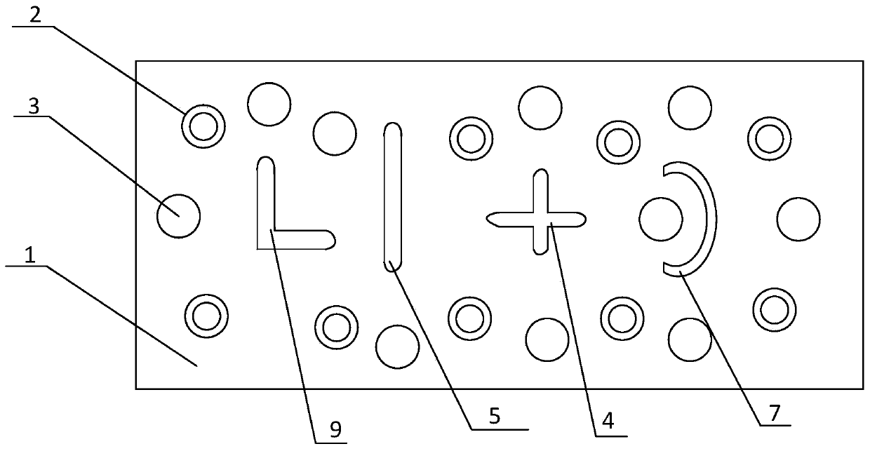
[0033] like image 3 As shown in the figure, a cross-coupling dielectric waveguide filter with 10th order and 6 notch waves includes a ceramic dielectric body 1, the ceramic dielectric body 1 is made of a high dielectric constant material, and the outer side of the ceramic dielectric body is formed by silver metallization to form a silver shield Floor. One side surface of the ceramic dielectric body 1 is provided with 5 groups of resonance holes, and each group of resonance holes includes two symmetrically arranged resonance blind holes 2 . Between the first group of resonant holes and the second group of resonant holes is set an L-shaped through slot 9 to form a coupling window; A cross-shaped through slot is arranged between the group of resonance holes and the fourth group of resonance holes, and the size of the arm slot of the cross-shaped through slot can be adjusted, so as to adjust the coupling amount between the two adjacent resonance holes 2; An arc-shaped through s...


PUM


Abstract

The invention relates to a cross-coupling dielectric waveguide filter, which comprises a ceramic dielectric body. A metal shielding layer is formed on the outer side of the ceramic dielectric body through metallization; a plurality of groups of resonance holes are formed in the surface of one side of the ceramic dielectric body; and each group of resonance holes comprises two resonance blind holeswhich are symmetrically formed. A through groove running through the ceramic dielectric body is formed between every two groups of resonant holes, and a plurality of resonant cavities are separated by the through grooves; the dielectric body is also provided with a plurality of coupling blind holes with adjustable sizes; a coupling window is formed between every two groups of resonance holes; andat least one through groove is an arc-shaped through groove and is matched with one coupling blind hole to form a cross coupling zero point. According to the invention, the problem of high rectangularity of the filter is solved; the integrated structure of the ceramic dielectric body is beneficial to miniaturization and consistency; and the arc-shaped through groove is formed in the resonant cavity in the dielectric body, and the position of the cross coupling zero point can be changed by adjusting the radian and the arc length of the arc-shaped through groove, so that out-of-band rejection is improved, and the influence on other communication frequency bands is reduced.

Description

technical field [0001] The invention belongs to the technical field of communication, and relates to a dielectric filter, in particular to a cross-coupling dielectric waveguide filter. Background technique [0002] The filter is an indispensable electronic component in the microwave communication system, and its performance determines the quality of the communication system. With the advent of 5G communication technology, the number of 5G base station antenna ports has increased from the traditional 8 ports to 64 ports and 128 ports, which greatly increases the demand for filters. Therefore, small-volume, lightweight, high-performance filters emerge as the times require and are imperative. The dielectric waveguide filter combines the excellent performance of cavity filters and traditional dielectric filters, so it has become the best choice for 5G communication equipment. [0003] The traditional waveguide filter is an air-filled metal cavity structure, and the edge of the...

Claims


Application Information

Patent Timeline
Patent Type & Authority Applications(China)
IPC IPC(8): H01P1/20H01P1/207
CPCH01P1/2002H01P1/207
Inventor 蒋廷利彭胜春靳文婷罗文汀黄骥
Owner CHINA ELECTRONICS TECH GRP NO 26 RES INST
Why Eureka
Try Eureka