Linear actuator

A technology of linear actuators and actuating elements, which is applied in the direction of transmission, electric components, and control/drive circuits, etc., which can solve the problems of high assembly cost and complex structure

Active Publication Date: 2020-02-21
LINAK AS
View PDF9 Cites 0 Cited by
  • Summary
  • Abstract
  • Description
  • Claims
  • Application Information

AI Technical Summary

Problems solved by technology

Both structures are complex and therefore expensive to assemble

Method used


Image

  • Linear actuator
  • Linear actuator
  • Linear actuator

Examples


Embodiment Construction

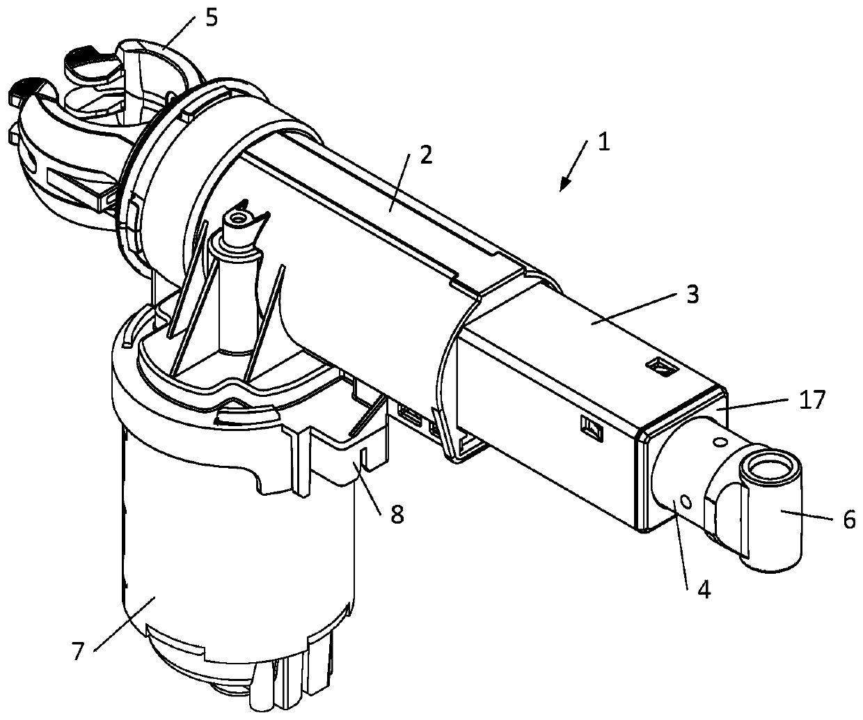
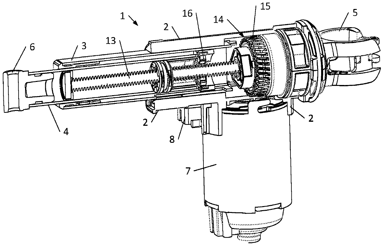
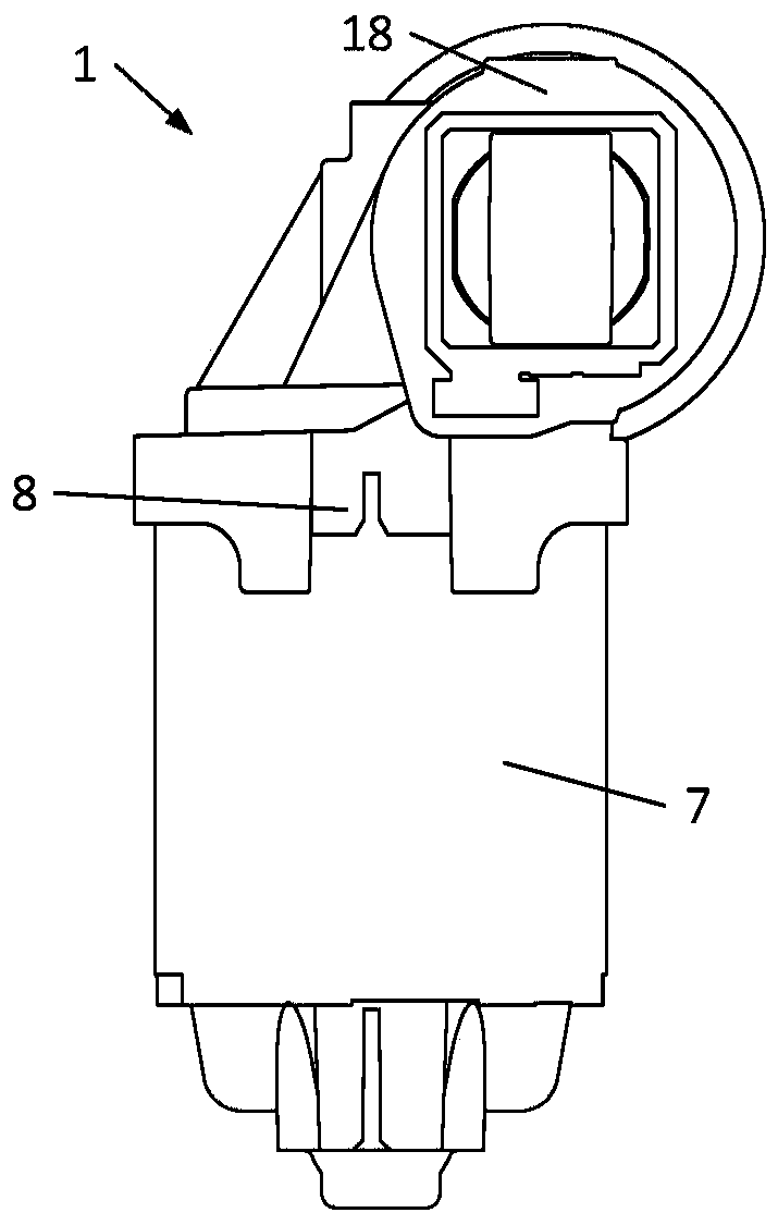
[0034] figure 1 A perspective view of a linear actuator 1 is shown comprising a console 2 , an outer tube 3 and an inner tube 4 guided in the outer tube 3 . For mounting the linear actuator, the rear end is equipped with a rear mount 5 and the front end of the inner tube 4 is equipped with a front mount 6 . Such as figure 1 and figure 2 As shown, the linear actuator 1 comprises a motor 7, typically a reversible motor, which may be a DC or AC motor for low or mains voltage. A motor 7 is mounted to the bottom of the console 2 , and a rear mount 5 is mounted to the rear end of the console 2 .

[0035] The linear actuator 1 comprises a socket 8 for connecting the linear actuator 1 to a power source or an electric controller.

[0036] The outer tube 3 comprises a rectangular section, in particular a square section, ie the outer tube 3 comprises four walls.

[0037] The linear actuator 1 also includes a main shaft 13, the main shaft 13 is driven by the motor 7 through a transm...


PUM


Abstract

The present invention relates to a linear actuator comprising a console, an outer tube connected to the console, an electric motor, a transmission, and a spindle in connection with the transmission. The linear actuator comprises a spindle nut on the spindle and an inner tube connected to the spindle nut. The spindle nut and the inner tube are guided inside the outer tube. The linear actuator comprises a control box which is connected to the console by means of a snap connection. The linear actuator further comprises an end stop arrangement having an end switch for each direction of movement ofthe spindle nut. An object underlying the invention is to provide a simpler connection of the control box to the linear actuator. A further object is to provide a less complex construction of the endstop arrangement of a linear actuator. To this end, the control box is connected to the console by means of a snap connection. Further, the linear actuator comprises a sliding element arranged between the spindle nut and the end switches, and where the sliding element is actuated by the spindle nut.

Description

technical field [0001] The invention relates to a linear actuator comprising a console, an outer tube connected to the console, a motor, a transmission and a spindle connected to the motor via the transmission. The linear actuator also includes a spindle nut on the spindle and an inner tube connected to the spindle nut. The spindle nut and inner tube are guided inside the outer tube and move along the longitudinal axis of the spindle, moving into or out of the outer tube depending on the direction of rotation of the motor. The linear actuator includes a control box connected to the console by a snap connection. The linear actuator also includes end stops having end switches for each direction of movement of the spindle nut. Background technique [0002] In a conventional linear actuator system comprising at least one linear actuator, a controller arranged in a control box, an operating unit and a power supply, these elements are connected by wires in a distributed system. ...

Claims


Application Information

Patent Timeline
IPC IPC(8): H02K5/22H02K7/06H02K11/20
CPCH02K5/225H02K7/06H02K11/20H02K11/30F16H2025/2084F16H2025/209
Inventor M·K·克努森H·斯科比R·索伦森
Owner LINAK AS
Why Eureka
Try Eureka