Shearing machine

A shearing machine and cutting table technology, which is applied in the direction of fabric surface trimming, textile material cutting, heating/cooling fabric, etc., can solve the problems of uneven cooling, increase of scrap fabrics, curling, etc., to achieve good cooling effect, cutting Good effect, the effect of reducing scrap rate

Inactive Publication Date: 2020-02-28
JIAXING BIANKA BAG & CASE
View PDF10 Cites 2 Cited by
  • Summary
  • Abstract
  • Description
  • Claims
  • Application Information

AI Technical Summary

Problems solved by technology

[0005] 1. After sticking the lining first, cut it directly, and then heat it to shape, it is easy to cause the fabric after the shape is not neat due to the shrinkage of the fabric, especially for some high-end fabrics, which increases the probability of scrapping the fabric;
[0006] 2. Because some fabrics have good toughness and good elasticity, the cutting device does not have a fixed limit structure, the cutting effect is not ideal, and the edges of the fabric are prone to irregularities;
[0007] 3. The cooling is not uniform enough, the cooling effect is not good enough, and it is prone to local curling

Method used


Image

  • Shearing machine

Examples


Embodiment 1

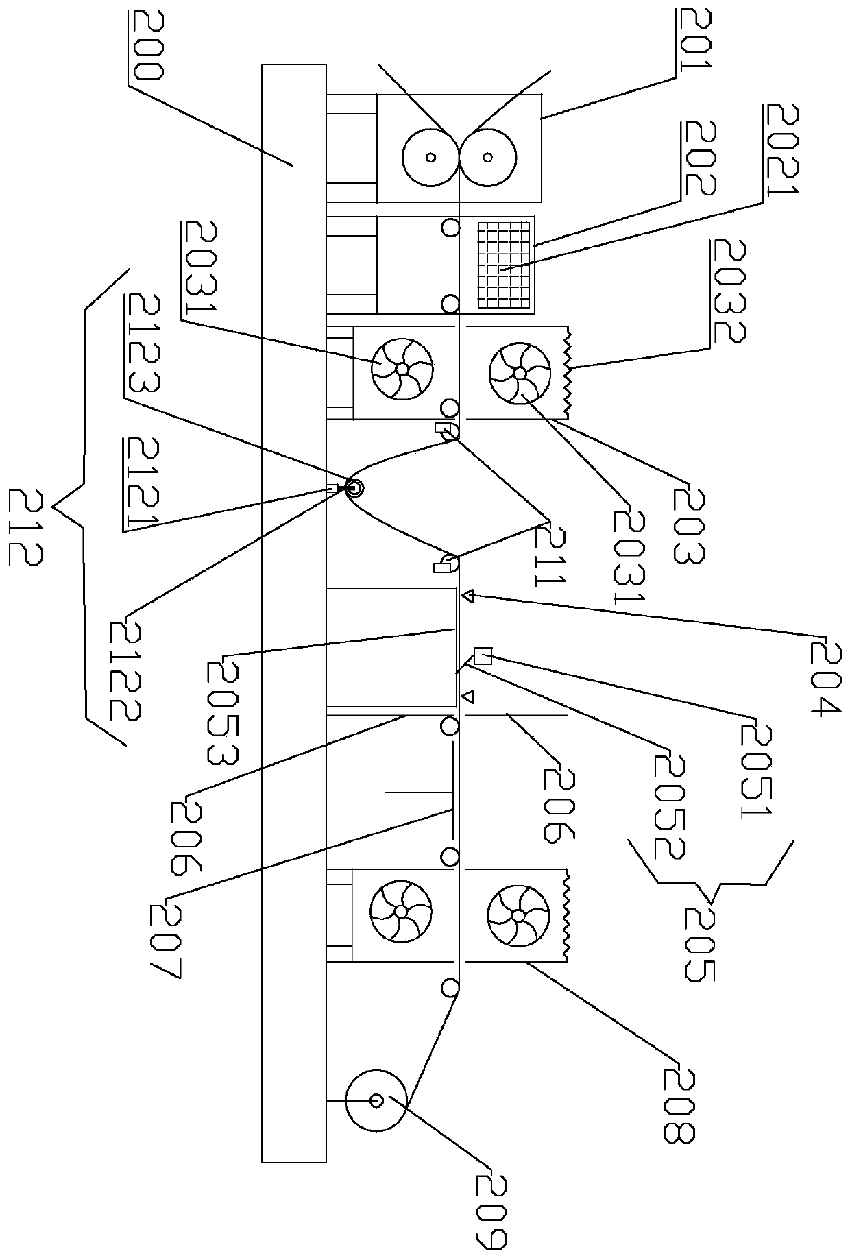
[0025] Such as figure 1 As shown, a shearing machine includes a shearing machine support table 200 and a lining device 201, a heating and setting device 202, a first cooling box 203, a cutting device 205, The steam ironing device 207, the second cooling box 208, and the winding roller 209; two support blocks 211 are arranged between the first cooling box 203 and the cutting device 205, and tensioning blocks 211 are provided between the support blocks 211 device 212; the tensioning device 212 includes a mounting base 2121, a floating link 2122 and a lightweight roller 2123; the cutting device 205 includes a knife rest 2051 and a cutter head 2052 that are symmetrically arranged on the front and rear sides, and the cutting device 205 A cutting table 2053 is provided below the cutting table 2053; above the cutting table 2053, and on the left and right sides of the cutting device 205, a pressing block 204 is arranged; between the pressing block 204 and the steam ironing device 207 ...

Embodiment 2

[0027] Such as figure 1 As shown, a shearing machine includes a shearing machine support table 200 and a lining device 201, a heating and setting device 202, a first cooling box 203, a cutting device 205, The steam ironing device 207, the second cooling box 208, and the winding roller 209; two support blocks 211 are arranged between the first cooling box 203 and the cutting device 205, and tensioning blocks 211 are provided between the support blocks 211 device 212; the tensioning device 212 includes a mounting base 2121, a floating link 2122 and a lightweight roller 2123; the cutting device 205 includes a knife rest 2051 and a cutter head 2052 that are symmetrically arranged on the front and rear sides, and the cutting device 205 A cutting table 2053 is provided below the cutting table 2053; above the cutting table 2053, and on the left and right sides of the cutting device 205, a pressing block 204 is arranged; between the pressing block 204 and the steam ironing device 207 ...


PUM


Abstract

The invention discloses a shearing machine. The shearing machine comprises a shearing machine supporting table as well as a lining sticking device, a heating and shaping device, a first cooling box, acutting device, a steam ironing device, a second cooling box and a winding roller which are sequentially arranged on the shearing machine supporting table; two supporting blocks are arranged betweenthe first cooling box and the cutting device, and a tensioning device is arranged between the supporting blocks; the cutting device comprises a knife rest and a knife head which are symmetrically arranged on the front side and the rear side, and a cutting table is arranged below the cutting device; a pressing block is arranged above the cutting table and on the left side and the right side of thecutting device; and a partition plate is arranged between the pressing block and the steam ironing device. By adoption of the shearing machine, the circumstance that the shaped fabric is not tidy enough due to shrinkage of the fabric can be avoided, especially for some high-end fabrics, the quality of the whole clothes is improved, and the rejection rate of the fabrics is effectively reduced.

Description

technical field [0001] The invention relates to the field of textile fabric processing machinery, in particular to a shearing machine. Background technique [0002] When making clothing fabrics, it is often necessary to stick a lining with viscose on the back of the fabric to make the clothing better quality, more comfortable and have a better dressing effect, and it is also convenient for sewing clothes. In some technologies, the fabric and the lining are usually aligned and cut by the lining machine, and then the fabric and the lining are heated and shaped at high temperature by the lining machine. Usually, the fabric made by this method will lead to irregular shaping and increase scrap The probability of the fabric, and there are too many steps in use, and the work efficiency is too low, which makes the cutting, alignment and bonding of the lining machine in the working process waste too much time, and also affects the quality of the whole garment. [0003] The State Int...

Claims


Application Information

Patent Timeline
Patent Type & Authority Applications(China)
IPC IPC(8): D06H7/00D06C7/02D06C7/00D06C15/00
CPCD06C7/00D06C7/02D06C15/00D06H7/00
Inventor 姚水英
Owner JIAXING BIANKA BAG & CASE
Why Eureka
Try Eureka