Stoping working face supporting-relief combined gob-side entry retaining roadway and construction method

A technology for mining working face and construction method, applied in tunnels, tunnel linings, mining equipment, etc., can solve the problems of long action time, high mining stress, difficult control of roadway surrounding rock, etc., and achieves overall strength and rigidity. High safety, fast and efficient support

Pending Publication Date: 2020-02-28
TIANDI SCI & TECH CO LTD
View PDF0 Cites 10 Cited by
  • Summary
  • Abstract
  • Description
  • Claims
  • Application Information

AI Technical Summary

Problems solved by technology

However, the gob-side entry retaining is affected by the mining of two working faces, the mining stres

Method used


Image

  • Stoping working face supporting-relief combined gob-side entry retaining roadway and construction method
  • Stoping working face supporting-relief combined gob-side entry retaining roadway and construction method
  • Stoping working face supporting-relief combined gob-side entry retaining roadway and construction method

Examples


Embodiment 1

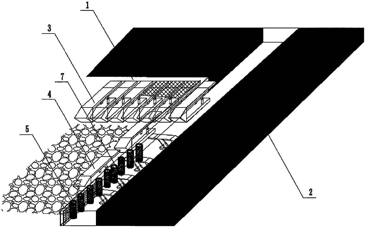
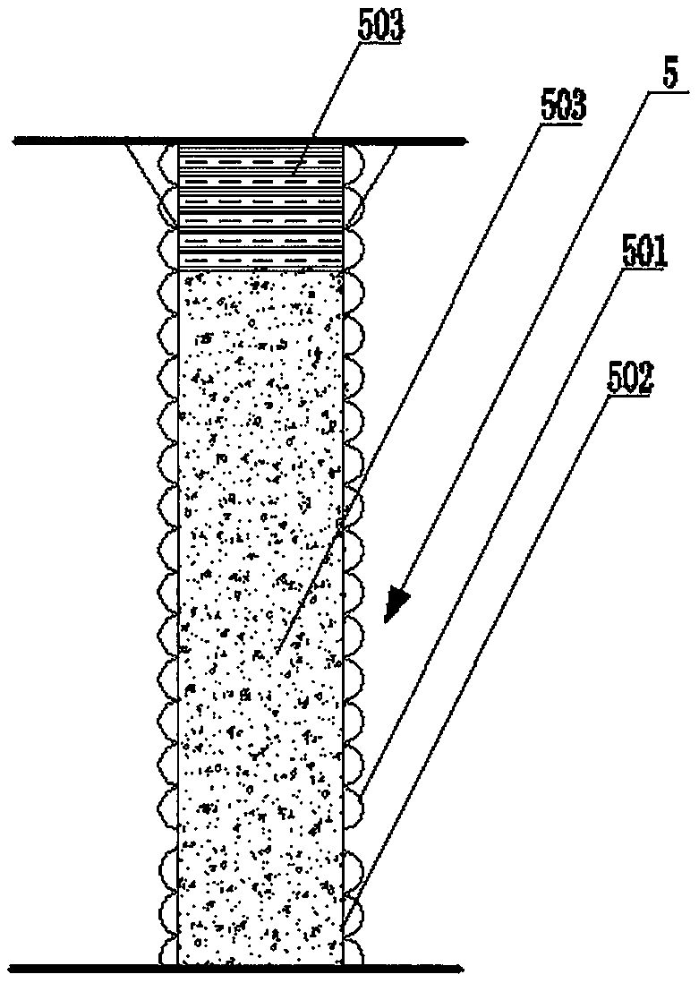
[0042] The "branch-unloading" combination gob-side entry roadway of the mining face is arranged between the goaf of the mining face 1 and the adjacent working face 2, on the side adjacent to the gob, on the side of the mining face 1 Behind the end support 3, close to the side of the goaf, along the direction of the roadway, there is a gangue-retaining hydraulic support 4 arranged close to the end support 3. A pier column 5 is arranged on the inside of the roadway, and the pier column 5 is firstly filled with concrete to a certain height, and then filled with a high-water material to ensure a crimped roof;
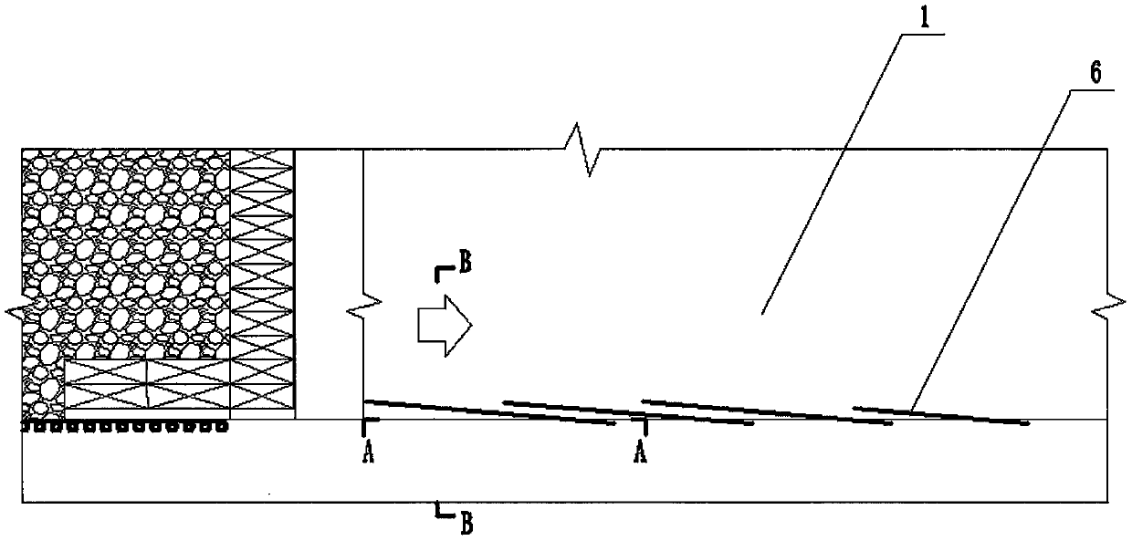
[0043] In the mining-affected area of ​​the advanced mining face 1 or the lagging gob-side entry roadway area, hydraulic pressure relief drillings 6 are arranged from the roadway to the roof.

[0044]In this embodiment, behind the end support 3, in the area where the pier column 5 is to be arranged, there is also a unit support 7, which is close to the side of the goaf.

...

Embodiment 2

[0057] This implementation is different from Embodiment 1 except that the following parts are different, and the rest are the same:

[0058] In this embodiment, a flexible bag mold 10 is fixed between the piers 5, and the flexible bag mold uses polymer foam filling material to form a continuous goaf isolation and closure wall with the piers 5.

[0059] The construction method of the present embodiment comprises the steps:

[0060] (a) According to the size requirements of the gob-side retaining roadway, determine the roadway excavation section of mining face 1 and the support method and parameters in the roadway;

[0061] (b) Hydraulic fracturing is used to relieve pressure on the roof in the mining-influenced area of ​​the advanced working face or in the lagging gob-side retaining roadway. The hydraulic fracturing drilling layout, parameters and construction technology are determined according to the lithology and structure of the roof ;

[0062] (c) During the recovery of ...


PUM


Abstract

The invention discloses a stoping working face supporting-relief combined gob-side entry retaining roadway. The stoping working face supporting-relief combined gob-side entry retaining roadway is arranged between a gob of a stoping working face and an adjacent working face, gangue-blocking hydraulic supports are arranged on the side adjacent to the gob and the side, close to the gob, behind an endsupport of the stoping working face along the trend of the roadway in the mode of closely following the end support, the gangue-blocking length is not less than the maximum daily pushing progress ofthe stoping working face, pier columns are arranged on the inner side, close to the gob, of the roadway, the pier columns are filled with concrete to a certain height, and then the pier columns are filled with high-water materials to ensure under-pressure roof contact; and in a mining-affected area of the advanced stoping working face or a lagging gob-side entry retaining roadway area, hydraulic pressure-relief drilled holes are formed from the roadway to a roof. The stoping working face supporting-relief combined gob-side entry retaining roadway is high in safety and reliability, high in construction speed, high in mechanization degree, low in cost and good in airtightness and has high adaptability to various geological conditions.

Description

technical field [0001] The invention relates to a "support-unloading" combined gob-side retaining roadway and a construction method in a mining face. Background technique [0002] The arrangement of gob-side entry retaining in the coal mining face has four major advantages: to realize coal pillar-free mining and increase the recovery rate of coal resources; to excavate less roadways and reduce the mine excavation rate; to implement a Y-shaped ventilation system in the mining face, which is conducive to solving the gas problem; Eliminate the adverse effects of stress concentration under the coal pillar on the mining of the lower coal seam and the support of the roadway when the coal pillar protects the roadway, so that the roadway is in the stress reduction zone for a long time. However, the gob-side entry retaining is affected by the mining of two working faces, the mining stress is high, the action time is long, and it is difficult to control the surrounding rock of the roa...

Claims


Application Information

Patent Timeline
IPC IPC(8): E21D9/00E21D9/14E21D11/15E21D11/10E21F15/08
CPCE21D9/00E21D9/14E21D11/10E21D11/152E21F15/08
Inventor 康红普吕华文王东攀马冰袁伟茗田锦州颜丙双王正胜刘跃东伊钟玉孙洋李帅乔军张辉吴志刚
Owner TIANDI SCI & TECH CO LTD
Why Eureka
Try Eureka