Depolarization gain ratio correction method for laser radar

A laser radar and calibration method technology, applied in radio wave measurement systems, instruments, etc., can solve the problems of low calibration efficiency, reduced reliability of moving parts, and long time consumption, so as to achieve high calibration efficiency, short time consumption, and improved reliability sexual effect

Active Publication Date: 2020-02-28
无锡中科光电技术有限公司
View PDF4 Cites 1 Cited by
  • Summary
  • Abstract
  • Description
  • Claims
  • Application Information

AI Technical Summary

Problems solved by technology

[0006] 1. Structural support is required, such as half-wave plates, etc., and the introduced moving parts reduce the reliability;
[0007] 2. It takes a long time and the calibration efficiency is low

Method used


Image

  • Depolarization gain ratio correction method for laser radar
  • Depolarization gain ratio correction method for laser radar
  • Depolarization gain ratio correction method for laser radar

Examples


Embodiment 1

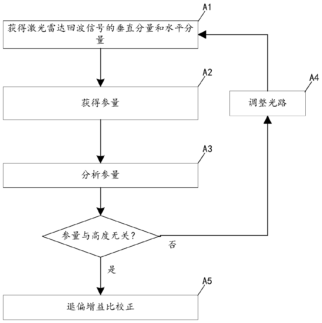
[0044] figure 1 A flow chart of the method for correcting the laser radar depolarization gain ratio in Embodiment 1 of the present invention is schematically given, as shown in figure 1 As shown, the correction method of the laser radar depolarization gain ratio includes the following steps:

[0045] (A1) Obtain the vertical component E of the lidar echo signal P (h) and the horizontal component E S (h), vertical component E P (h) and the horizontal component E S (h) are respectively the components to deduct the noise;

[0046] (A2) Get parameters

[0047] (A3) Analysis of said parameter ε(h):

[0048] if h>h 0 When the parameter ε(h) has nothing to do with the height h, h 0 Be the atmospheric boundary layer height, enter step (A5);

[0049] if h>h 0 When the parameter ε (h) is relevant to the height h, enter step (A4);

[0050] (A4) Adjust the transmitting optical path and receiving optical path of the lidar so that the transmitting optical path and the receiving...

Embodiment 2

[0073] An application example of the method for correcting the laser radar depolarization gain ratio according to Embodiment 1 of the present invention.

[0074] In this application example, in the optical path adjustment of step (A4), the specific method is: adjust the laser radar transmitting optical path and / or receiving optical path: the measuring light emitted by the laser passes through the beam expander unit, the double wedge prism (two prisms) After the inclined surface is oppositely set), it is reflected by the first reflector and the second reflector in turn, so as to enter the atmosphere; by adjusting the double wedge prism, the outgoing direction of the measuring light on the second reflector is changed, so that the The emitting light path and the receiving light path are coaxial.

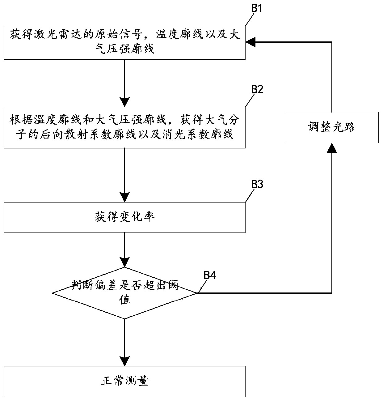
[0075] Validation schemes for lidar data include:

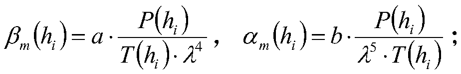
[0076] (B1) Obtain the original signal P of the lidar lidar (h i ),Specifically:

[0077]

[0078] Among them, i=1,2,3,...n, h...


PUM


Abstract

The invention provides a depolarization gain ratio correction method for a laser radar. The method comprises the following steps: (A1) obtaining a vertical component EP(h) and a horizontal component ES(h) of a laser radar echo signal; (A2) obtaining parameters; (A3) analyzing the parameter epsilon(h): if the parameter epsilon(h) is not related to the height h when h is greater than h0, and the h0is the height of the atmospheric boundary layer, entering the step (A5); if the parameter epsilon(h) when h is greater than h0 is related to the height h, executing the step (A4); (A4) adjusting a transmitting light path and a receiving light path of the laser radar, and entering the step (A1); (A5) correcting the depolarization gain ratio k to be the depolarization ratio of the atmospheric molecules when h is greater than h0, wherein epsilon1 is the average value of the parameters when h is greater than h0. The method has the advantages of simplicity, convenience and the like.

Description

technical field [0001] The invention relates to a laser radar, in particular to a correction method for the depolarization gain ratio of the laser radar. Background technique [0002] Lidar is a detection device with laser as the light source. When the laser beam emitted by it is transmitted in the atmosphere, it is attenuated by the atmosphere on the transmission path (mainly from the extinction of atmospheric aerosol molecules and atmospheric molecules), and part of it is absorbed by the aerosol The laser scattered by the air molecules returns along the original path, and is attenuated by the atmosphere on the transmission path again, and finally received by the lidar. As an important technical means to detect the temporal and spatial distribution of atmospheric particles and clouds, lidar detection data are of great significance to the study of the vertical distribution, migration and diffusion process of aerosols, the atmospheric boundary layer and its temporal and spati...

Claims


Application Information

Patent Timeline
Patent Type & Authority Applications(China)
IPC IPC(8): G01S7/497
CPCG01S7/497Y02A90/10
Inventor 万学平李岭高洁潘浩王界陈晓龙曲洪丰
Owner 无锡中科光电技术有限公司
Why Eureka
Try Eureka