
Circulating oil gas separation method

A separation method, oil and gas technology, applied in separation methods, dispersed particle separation, chemical instruments and methods, etc., can solve problems such as a large amount of waste water, secondary pollution treatment costs, and inadequate treatment.

Inactive Publication Date: 2020-03-06
江苏中远环保科技有限公司
View PDF9 Cites 0 Cited by
  • Summary
  • Abstract
  • Description
  • Claims
  • Application Information

AI Technical Summary

Problems solved by technology

[0003] At present, the tank washing waste gas produced in this field in our country is basically untreated and discharged directly. In some cases, washing + adsorption method, low temperature plasma removal method, and oxidative incineration method are used. These treatment methods can achieve certain effects, but there are often problems with treatment. In place, a large amount of waste water is generated, causing secondary pollution and high treatment costs

Method used


Image

  • Circulating oil gas separation method

Examples


Embodiment Construction

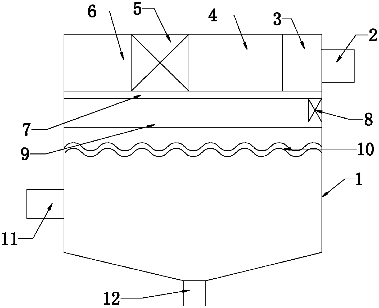
[0017] The circulating oil-gas separation method of the present invention will be further described in detail below in conjunction with the accompanying drawings and specific embodiments.

[0018] As shown in the figure, the circulating oil-gas separation method of the present invention comprises the following steps:

[0019] A. The oil and gas are initially condensed (the condensation temperature is -1—-5°C) and then enter the shell 1 through the air inlet 2. During this process, the flow into the shell is controlled by the control valve;

[0020] B. The oil and gas entering the shell is filtered by the filter 3 in the shell and adsorbed by the adsorption chamber (the adsorption chamber 4 is arranged with multiple groups of adsorption materials side by side), and then enters the heating chamber 5 to be heated by the heating device. The heating temperature is 210-230°C, the heated oil and gas are sent to the air supply pipeline 7 through the induced draft fan in the induced ai...


PUM


Abstract

The invention discloses a circulating oil gas separation method. The method comprises the following steps: A, primarily condensing oil gas and then feeding the condensed oil gas into a shell; B, filtering the condensed oil gas through a filter and adsorbing the filtered oil gas through an adsorption cavity, then feeding the adsorbed oil gas into a heating cavity for heating, and sending the heatedoil gas into a gas delivery pipeline; C, condensing the heated oil gas in a condenser again, feeding the condensed oil gas into a condensing pipeline, and discharging the condensed oil gas from an exhaust hole; and D, dispersing the oil gas discharged from the exhaust hole by blocking through an oil blocking plate below the exhaust hole. After the method is adopted, layer-by-layer filtration canbe carried out through each layer of structures, and multi-layer oil dropping by condensation can be realized through a specific measure of high-temperature heating and direct low-temperature condensation to the maximum degree in the filtration process, so that gas has a very good filtration effect. In addition, the whole oil gas separation process has a plurality of treatment measures, so that oil gas can be thoroughly separated and collected in a pure manner, the separation effect is good, energy consumption is very low, and thus treatment cost is greatly reduced.

Description

technical field [0001] The invention relates to an oil-gas separation device, in particular to a circulating oil-gas separation method. Background technique [0002] In the process of waste gas recovery and treatment in oil depots, refineries, wharfs and other oil product shipments, trains, cars, tank cars, tankers, oil tanks, oil storage tanks, etc. are washed and cleaned regularly before changing the storage quality The volatilized toxic and harmful waste gas is recycled into liquid oil, which can avoid the discharge of a large amount of pollutants and has greater recycling economic benefits. [0003] At present, the tank washing waste gas produced in this field in our country is basically untreated and discharged directly. In some cases, washing + adsorption method, low temperature plasma removal method, and oxidative incineration method are used. These treatment methods can achieve certain effects, but there are often problems with treatment. If it is in place, a large ...

Claims


Application Information

Patent Timeline
IPC IPC(8): B01D53/00B01D46/00B01D53/02B01D53/26
CPCB01D46/00B01D53/002B01D53/005B01D53/02B01D53/26B01D2257/80
Inventor 徐广林王友红奚雯杰
Owner 江苏中远环保科技有限公司
Learn More