High-precision 3D sand mold printing equipment

A printing equipment and high-precision technology, applied in the field of 3D printing, can solve problems such as the inability to comprehensively consider the uniformity of sand laying, the recovery of residual sand from sand surface settlement, affecting the preparation quality and efficiency of sand mold parts, and the complexity of the overall structure, and achieve automation. The effect of high degree, convenient collection and high dimensional accuracy

Inactive Publication Date: 2020-03-06
郑州中兴三维科技有限公司
View PDF8 Cites 7 Cited by
  • Summary
  • Abstract
  • Description
  • Claims
  • Application Information

AI Technical Summary

Problems solved by technology

[0004] The existing sand mold 3D printers have a complex overall structure and a low degree of automation, and cannot comprehensively consider issues such as sand laying uniformity, sand surface settlement, and residual sand recovery, which affects the quality and efficiency of sand mold parts preparation

Method used


Image

  • High-precision 3D sand mold printing equipment
  • High-precision 3D sand mold printing equipment
  • High-precision 3D sand mold printing equipment

Examples


Embodiment 1

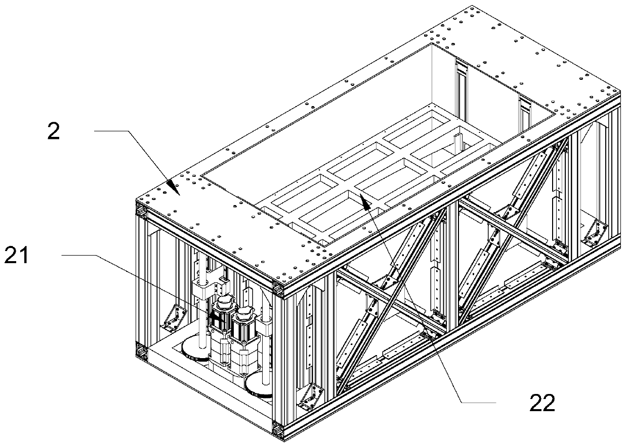
[0041] combine figure 1 and Figure 5 , a high-precision 3D sand printing device, including a support frame 1, a sand box 2, an inkjet assembly 3 and a sand delivery assembly 4, the sand box 2 is arranged inside the support frame 1, the inkjet assembly 3 and the sand delivery assembly The sand assembly 4 is arranged on the upper end of the support frame 1 , and the inkjet assembly 3 and the sand delivery assembly 4 correspond to the sand box 2 .

[0042]The inkjet assembly 3 includes an inkjet trolley 32, a first guide rail 31 and a second guide rail 33, the inkjet trolley 32 is slidably connected to the first guide rail 31, and the two ends of the first guide rail 31 are slidably connected to the second guide rail 31 through a bracket. The guide rail 33 , the first guide rail 31 is arranged perpendicular to the second guide rail 33 , and the second guide rail 33 is arranged on the upper end of the supporting frame 1 .

Embodiment 2

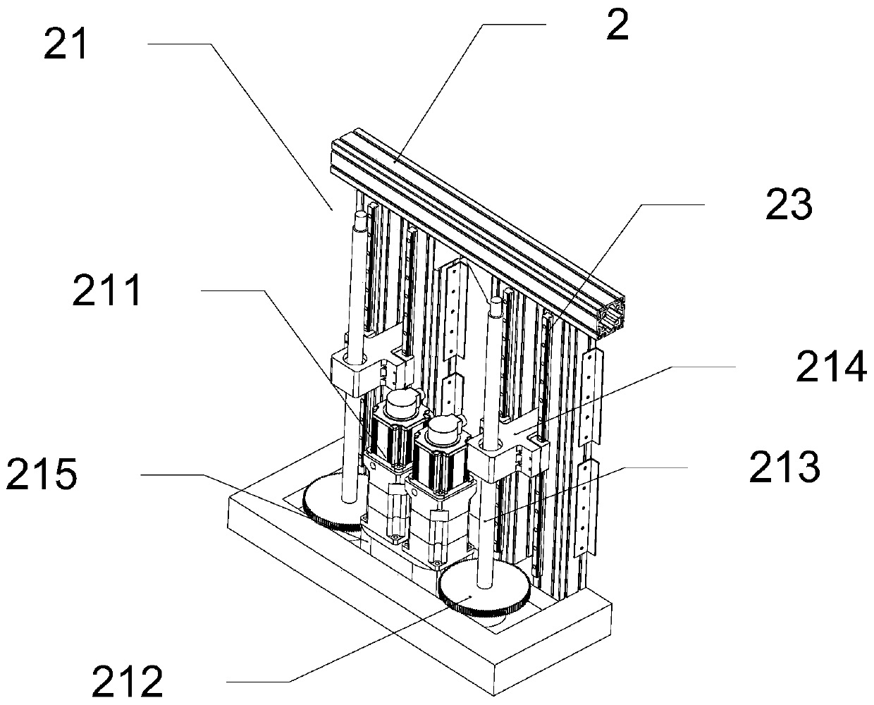
[0044] like Figure 2-4 As shown, the outer two ends of the sand box 2 are provided with slide rails 23 and a lifting mechanism 21, and the inside of the sand box 2 is provided with a lifter 22 connected with the lifting mechanism 21, and the lifting mechanism 21 is connected by the slide rail 23. Die frame 22, described elevating mechanism 21 comprises base 215, drive motor 211, ball screw pair 213 and sliding frame 214, and described base 215 is located at sandbox 2 bottom, and described drive motor 211 and ball screw pair 213 all Located on the upper end of the base 215, the output shaft of the drive motor 211 is connected to the bottom of the ball screw pair 213 through the sprocket 212, the sliding frame 214 is sleeved on the outside of the ball screw pair 213, and the ejector frame 22 The sliding frame 214 is slidably connected to the sliding rail 23, the sand box 2 is a box structure with an upper end open, and the ejector frame 22 is a square grid with several uniform ...

Embodiment 3

[0048] like Image 6 As shown, the inkjet assembly 3 includes an inkjet trolley 32, a first guide rail 31 and a second guide rail 33, the inkjet trolley 32 is slidably connected to the first guide rail 31, and the two ends of the first guide rail 31 slide through brackets Connected to the second guide rail 33 , the first guide rail 31 is arranged perpendicular to the second guide rail 33 , and the second guide rail 33 is arranged on the upper end of the supporting frame 1 .

[0049] The inkjet cart 32 includes a housing 321, an inkjet mechanism and a nozzle mechanism, the inkjet mechanism is arranged at the upper end of the housing 321, the nozzle mechanism is arranged at the lower end of the housing 321, and the inkjet mechanism Corresponding to the nozzle mechanism.

[0050] The inkjet mechanism includes a syringe pump 322, an ink cartridge 323 and an ink outlet hole 324. The output end of the syringe pump 322 is connected to the input end of the ink cartridge 323, and the ...


PUM


Abstract

The invention relates to high-precision 3D sand mold printing equipment. The high-precision 3D sand mold printing equipment comprises a support frame, a sand box, an ink jet assembly and a sand feeding assembly, wherein sliding rails and lifting mechanisms are arranged at the two outer ends of the sand box; a mould lifting frame connected with the lifting mechanisms is arranged in the sand box; the ink jet assembly comprises an ink jet trolley, a first guide rail and second guide rails; the ink jet trolley is connected with the first guide rail; the two ends of the first guide rail are connected with the second guide rails; the second guide rails are arranged at the upper end of the support frame; the sand feeding assembly comprises a sand storage tank, a spiral rod, a scraper and a vibration motor; the two ends of the sand storage tank are slidably connected with third guide rails; the spiral rod is arranged inside the sand storage tank; and the scraper and the vibration motor are respectively arranged on the two sides of the bottom of the sand storage tank. According to the printing equipment provided by the invention, through the cooperation of the ink jet assembly, the sand feeding assembly and the sand box, the actions of automatic sand spreading, printing, sand surface sedimentation, residual sand collection and the like can be realized, the automation degree is high, andthe rapid forming of any complex part can be realized.

Description

technical field [0001] The invention belongs to the technical field of 3D printing, and in particular relates to a high-precision 3D sand printing device. Background technique [0002] The foundry industry is a labor-intensive, high-energy-consumption, and high-pollution industry. The foundry industry needs to focus on research and adoption, promote advanced casting technology and introduce other advanced technologies, seek a combination with advanced technology to change the status quo of the foundry industry, and realize the foundry industry to low energy consumption. , low pollution and high quality. [0003] With the development of 3D printing technology today, its development focus has shifted from 3D printing prototypes to rapid manufacturing and rapid direct manufacturing of metal parts. 3D printing technology is not only used in the design process, but also extends to the manufacturing field. In manufacturing, The main factor that limits the time for products to mar...

Claims


Application Information

Patent Timeline
IPC IPC(8): B22C9/02B33Y30/00B33Y40/00B33Y80/00
CPCB22C9/02B33Y30/00B33Y40/00B33Y80/00Y02P10/25
Inventor 刘中兴吴阳王洪毅刘印
Owner 郑州中兴三维科技有限公司
Why Eureka
Try Eureka