Stirring device for building construction

A technology for building construction and mixing devices, which is applied in cement mixing devices, clay preparation devices, and sales of raw material supply devices, etc. It can solve the problems that sandstones with different hardness cannot be screened and crushed, cannot meet the needs of construction, and increase the labor intensity of workers. , to achieve the effect of meeting the needs of building use, multiple functions, and reducing labor intensity

Inactive Publication Date: 2020-03-06
ZHEJIANG COLLEGE OF CONSTR
View PDF0 Cites 19 Cited by
  • Summary
  • Abstract
  • Description
  • Claims
  • Application Information

AI Technical Summary

Problems solved by technology

[0002] A large amount of concrete is used in the process of building construction. Concrete refers to the general designation of engineering composite materials that use cementitious materials to cement aggregates into a whole. The term concrete usually refers to the use of cement as cementitious material and sand and stone as bone. Material; mixed with water (may contain admixtures and admixtures) in a certain proportion, the cement concrete obtained by mixing is also called ordinary concrete. It is widely used in construction projects. The mixing and mixing of concrete is generally done by using concrete mixing equipment. Completed, but the existing concrete mixing equipment generally only mixes various materials together for simple mixing, and there are problems of uneven and incomplete mixing. At the same time, the existing concrete mixing equipment cannot screen and crush sandstones with different hardness. If it is accidentally mixed into the cement soil, the quality of the concrete will be affected. Separate crushing will increase the labor intensity of the workers and cannot meet the needs of construction.

Method used


Image

  • Stirring device for building construction
  • Stirring device for building construction
  • Stirring device for building construction

Examples


Embodiment Construction

[0015] The present invention will be described in further detail below in conjunction with the accompanying drawings and specific embodiments:

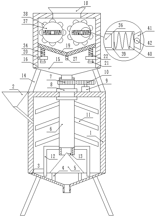
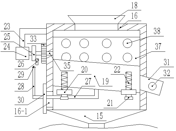
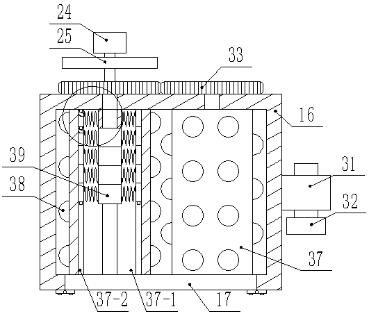
[0016] like figure 1 , figure 2 , image 3 , Figure 4As shown, a stirring device for building construction includes a mixing tank 1, the side wall of the mixing tank 1 is fixedly connected with a feed funnel 2, and the bottom end of the mixing tank 1 is fixedly connected with a first funnel 3, and the first The bottom end of the funnel 3 is threadedly connected with a cover body, the bottom end of the first funnel 3 is fixedly and symmetrically connected with a plurality of legs, the inner wall of the first funnel 3 is symmetrically fixedly connected with two vertical rods 4, and the top ends of the two vertical rods 4 are fixedly connected There is a conical block 5, and a vertical pipe 6 is arranged directly above the conical block 5. The top of the vertical pipe 6 passes through the mixing tank 1 and is fixedly covered with a ...


PUM


Abstract

The invention discloses a stirring device for building construction. The stirring device for building construction comprises a stirring barrel, the top end of a crushing barrel fixedly communicates with a feeding pipe, the two side walls of a barrel body are symmetrically and fixedly connected with second springs, two dovetail grooves are located on the two sides of a second through groove and communicate with the second through groove, a plurality of dovetail blocks are arranged in each dovetail groove in a attached and sliding mode, the other ends of the second springs are fixedly connectedwith the side walls of the dovetail blocks, one sides of the dovetail blocks are provided with blind holes, the other sides of the dovetail blocks are fixedly connected with inserting rods matched with the blind holes, the inserting rods are made of a Fe3O4 material, a first rotating shaft and a second rotating shaft are connected in a welded mode, and the model of a three-phase asynchronous motoris Y2-80M2-4S150. The device is diversified in function and high in practicability, concrete can be fully stirred and then can be uniformly mixed, the quality of the finished product is improved, stones with different hardness can be crushed and screened according to different requirements, so that the utilization rate of the stones is improved, then the quality of the concrete is indirectly improved, the labor intensity is reduced, and the building use requirement is met.

Description

technical field [0001] The invention relates to the field of construction, in particular to a stirring device for building construction. Background technique [0002] Concrete is widely used in the construction process. Concrete refers to the collective name of engineering composite materials that are cemented by cementing materials to form a whole. The term concrete usually refers to the use of cement as cementing material and sand and stone as bone. Mixed with water (which may contain admixtures and admixtures) in a certain proportion, the cement concrete obtained by mixing, also known as ordinary concrete, is widely used in construction projects. The mixing and mixing of concrete is generally made by using concrete mixing equipment Completed, but the existing concrete mixing equipment generally only mixes various materials together and simply mixes, and there is a problem of uneven and incomplete mixing. Slightly inadvertently mixed into the cement and soil, thus affecti...

Claims


Application Information

Patent Timeline
Patent Type & Authority Applications(China)
IPC IPC(8): B28C5/16B28C5/08B28C7/00B28C7/06B02C4/08B02C4/30B02C4/42B02C23/16B07B1/34B07B1/42B07B1/44B07B1/46
CPCB02C4/08B02C4/30B02C4/42B02C23/16B02C2023/165B07B1/34B07B1/42B07B1/44B07B1/46B28C5/0806B28C5/16B28C7/0007B28C7/06
Inventor 俞嘉陈
Owner ZHEJIANG COLLEGE OF CONSTR
Why Eureka
Try Eureka