Gypsum calcinator and working principle

A calciner and gypsum technology, which is applied in the field of gypsum production equipment, can solve the problems of affecting the properties of powder materials, over-burning, and uneven distribution of powder materials, and achieve the effects of improving quality, avoiding local over-burning, and reducing impurities

Pending Publication Date: 2020-03-06
CHINA NAT BUILDING MATERIALS TECHCAL INNOVATION & RES INST LIMITED
View PDF0 Cites 1 Cited by
  • Summary
  • Abstract
  • Description
  • Claims
  • Application Information

AI Technical Summary

Problems solved by technology

However, in the second-step calcination equipment (calciner), the powder is often unevenly distributed in the calcinator, resulting in local over-burning, which affects the properties of the powder

Method used


Image

  • Gypsum calcinator and working principle
  • Gypsum calcinator and working principle

Examples


Embodiment 1

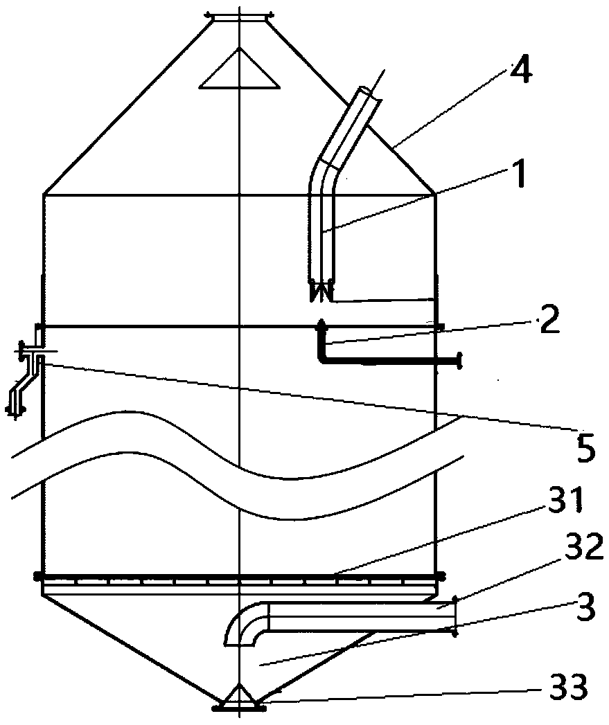
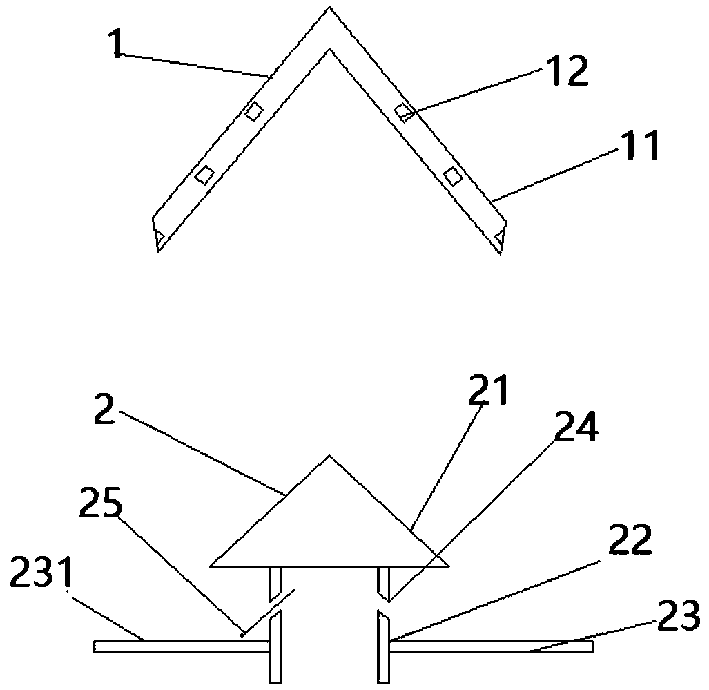
[0041] A gypsum calciner, the diameter of the first bulk material cap 11 of the feeding device 1 can be 1.2 times the diameter of the second bulk material cap 21 of the bottom blowing device 2, and the inclined multiple air holes 24 of the bottom blowing device The angle between the extension line 25 and the air uniform plate 23 can be 8°, and the surface roughness of the air uniform plate 23 of the bottom blowing device is 0.1.

Embodiment 2

[0043] A gypsum calciner, the diameter of the first bulk material cap 11 of the feeding device 1 can be 0.9 times the diameter of the second bulk material cap 21 of the bottom blowing device 2, and the inclined multiple air holes 24 of the bottom blowing device The angle between the extension line 25 and the air uniform plate 23 can be 45°, and the surface roughness of the air uniform plate 23 of the bottom blowing device is 0.5.

Embodiment 3

[0045] A gypsum calciner, the diameter of the first bulk material cap 11 of the feeding device 1 can be 0.8 times the diameter of the second bulk material cap 21 of the bottom blowing device 2, and the inclined multiple air holes 24 of the bottom blowing device The angle between the extension line 25 and the air uniform plate 23 can be 20°, and the surface roughness of the air uniform plate 23 of the bottom blowing device is 0.05.


PUM


Abstract

The invention provides a gypsum calcinator which comprises a feeding device (1), a bottom blowing device (2) and an air evening device (3) which are arranged from top to bottom in sequence, wherein the feeding device (1) comprises a first dispersing cap (11) for primarily dispersing a gypsum powder material conveyed into the shell (4) and a plurality of falling through holes (12) which are uniformly distributed in the first dispersing cap (11); and the bottom blowing device (2) comprises a secondary dispersing cap (21) for secondarily dispersing the primarily dispersed gypsum powder material,an air allocation tube (22), an air evening plate (23) and a plurality of vent holes (24) which are uniformly distributed in the air allocation tube (22) between the secondary dispersing cap (21) andthe secondary dispersing cap (21). By adopting the device, gypsum powder conveyed into the gypsum calcinator is dispersed into a fluidization state, so that the consequence that the properties of a powder material are affected by partial over-calcination in the gypsum calcinator can be avoided.

Description

technical field [0001] The invention relates to a gypsum production device, in particular to a gypsum calciner and its working principle. Background technique [0002] In the calcination process of gypsum, the "two-step method" process has a uniform and stable calcination process, and the calcined gypsum has high active ingredients and good bleeding properties, and the setting time of subsequent production molding is easy to adjust. Therefore, it is widely used. However, in the second-step calcination equipment (calciner), often due to the uneven distribution of the powder in the calcinator, local over-burning is caused, which affects the properties of the powder. Contents of the invention [0003] In view of the above problems, the present invention aims to solve the problems described above. An object of the present invention is to provide a gypsum calciner that solves the above problems. By breaking up and fluidizing the gypsum powder delivered to the gypsum calciner,...

Claims


Application Information

Patent Timeline
IPC IPC(8): C04B11/036
CPCC04B11/036
Inventor 杨正波张羽飞侯志刚任有欢李绍冉
Owner CHINA NAT BUILDING MATERIALS TECHCAL INNOVATION & RES INST LIMITED
Why Eureka
Try Eureka