Check patentability & draft patents in minutes with Patsnap Eureka AI!

Air compressor waste heat conversion and utilization equipment

A technology of waste heat conversion and air compressor, which is applied in the direction of mechanical equipment, machine/engine, liquid variable capacity machinery, etc., can solve the problem of wasting resources, and achieve the effect of saving resources, protecting the environment and protecting equipment

Inactive Publication Date: 2020-03-06
孙萍
View PDF8 Cites 0 Cited by
  • Summary
  • Abstract
  • Description
  • Claims
  • Application Information

AI Technical Summary

Problems solved by technology

[0004] In order to overcome the shortcomings of waste of resources in the current air compressor water cooling method, the technical problem to be solved is: to provide an air compressor waste heat conversion and utilization equipment that saves energy and reduces production costs

Method used


Image

  • Air compressor waste heat conversion and utilization equipment
  • Air compressor waste heat conversion and utilization equipment
  • Air compressor waste heat conversion and utilization equipment

Examples


Embodiment 1

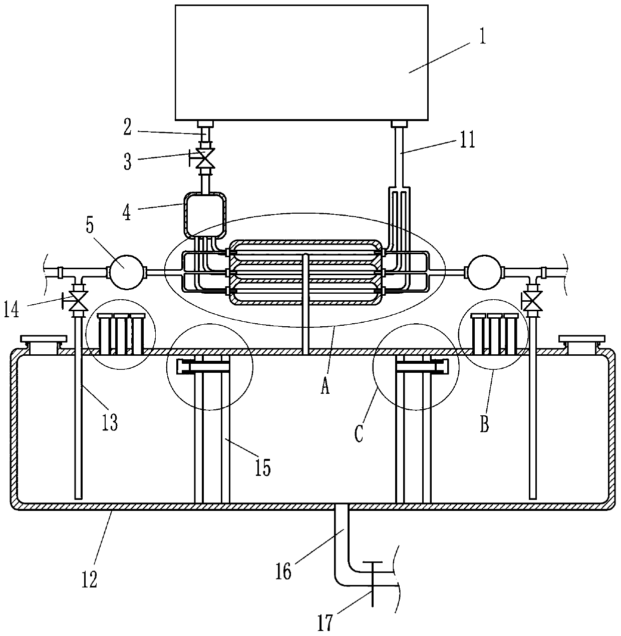
[0018] Such as figure 1 and 2 As shown, an air compressor waste heat conversion and utilization equipment includes an air compressor 1, an oil outlet pipe 2, a first battery valve 3, an oil circuit cooling component, an oil inlet pipe 11 and a water resource recycling component. An oil outlet pipe 2 and an oil inlet pipe 11 are installed, the first battery valve 3 is installed on the oil outlet pipe 2, and an oil circuit cooling component for cooling the oil circuit through water cooling is installed between the oil outlet pipe 2 and the oil inlet pipe 11, the oil circuit cooling A water resource reuse component is installed below the component.

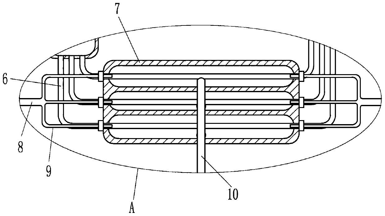
[0019] Such as figure 1 and 2 As shown, the oil circuit cooling components include a distribution frame 4, a water pump 5, an oil distribution pipe 6, a cooling box 7, a main water pipe 8, a water distribution pipe 9 and a water outlet pipe 10. The distribution frame 4 is installed at the outlet of the oil outlet pipe 2, and the b...

Embodiment 2

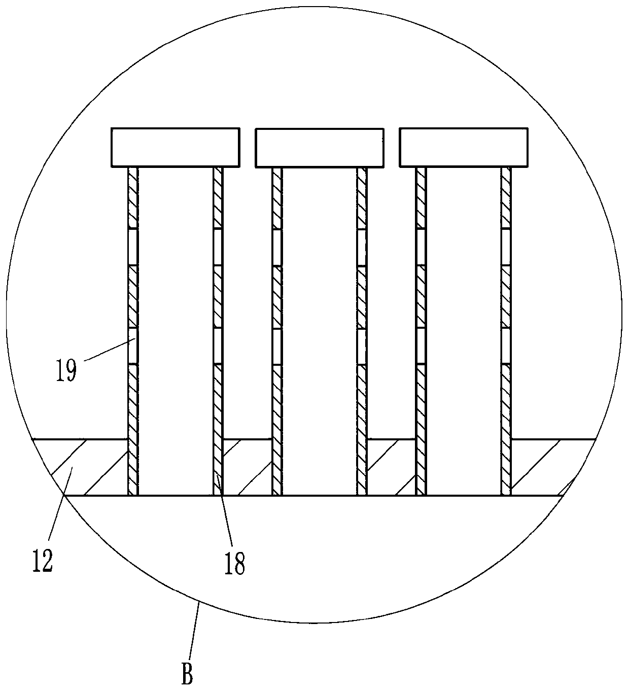
[0025] Such as figure 1 and 3 As shown, on the basis of Embodiment 1, in order to speed up the cooling of the water and use it in time, an air outlet pipe 18 is also included. Three air outlet pipes 18 are arranged on the left and right sides of the upper wall of the water tank 12, and there are two circles on the air outlet pipe 18. Cooling hole 19.

[0026] Such as figure 1 and 4 As shown, in order to prevent the loss of hot water heat, it also includes a moving plug 21 and a spring 22. The overflow pipe 151 has a water outlet hole 20 on the outside of the bottom. The overflow pipe 151 is equipped with a moving plug 21. The moving plug 21 can slide left and right. The moving plug 21 blocks the water outlet hole 20 , and a spring 22 is connected between the moving plug 21 and the overflow pipe 151 .

[0027] In the specific implementation manner of the above-mentioned embodiment, when water enters the water tank 12, it can dissipate heat through the cooling holes 19, so t...


PUM


Abstract

The invention relates to conversion and utilization equipment, in particular to air compressor waste heat conversion and utilization equipment in order to achieve the technical effects of saving energy and reducing the production cost. The air compressor waste heat conversion and utilization equipment comprises an air compressor, an oil outlet pipe, a first battery valve, an oil way cooling component and the like. The air compressor is provided with the oil outlet pipe and an oil inlet pipe. The first battery valve is mounted on the oil outlet pipe. The oil way cooling component used for cooling an oil way in a water-cooling mode is mounted between the oil outlet pipe and the oil inlet pipe. The air compressor waste heat conversion and utilization equipment can separate oil through the oilway cooling component, so that the contact area of oil and water is larger, and the oil cooling speed can be increased. Through a water resource reutilization component, the air compressor waste heatconversion and utilization equipment can separate hot water from cold water so that the cold water can go into the oil way cooling component for reuse.

Description

technical field [0001] The invention relates to conversion and utilization equipment, in particular to an air compressor waste heat conversion and utilization equipment. Background technique [0002] An air compressor is a device used to compress gas. Air compressors are similar in construction to water pumps. Most air compressors are reciprocating piston, rotary vane or rotary screw. Centrifugal compressors are very large applications. The oil circuit of the air compressor needs to be cooled, and water cooling is generally used now. [0003] Now when cooling the oil circuit of the air compressor, a water cooling device is installed on the oil circuit. When the oil passes through the cooling device, the cooling device cools the oil in the oil circuit. Because of the water cooling method, the water used to cool the oil circuit The temperature rises rapidly, such water cannot be used immediately, so it needs to be replenished with new water, and the water with elevated tem...

Claims


Application Information

Patent Timeline
IPC IPC(8): F04B39/06F04B39/02
CPCF04B39/02F04B39/06
Inventor 孙萍
Owner 孙萍
Features
  • R&D
  • Intellectual Property
  • Life Sciences
  • Materials
  • Tech Scout
  • Unparalleled Data Quality
  • Higher Quality Content
  • 60% Fewer Hallucinations
Learn More