Check patentability & draft patents in minutes with Patsnap Eureka AI!

Delay phase-locked loop and phase discriminator circuit thereof

A phase detector and phase-locked loop technology, applied in the direction of electrical components, automatic power control, etc., can solve the problems of long reset path and large overall power consumption of the phase detector circuit, shorten the reset path, reduce overall power consumption and The effect of increasing the area and phase identification speed

Pending Publication Date: 2020-03-06
XIAN UNIV OF POSTS & TELECOMM
View PDF9 Cites 0 Cited by
  • Summary
  • Abstract
  • Description
  • Claims
  • Application Information

AI Technical Summary

Problems solved by technology

[0005] The purpose of the present invention is to provide a delay phase-locked loop and a phase detector circuit thereof, to solve the above-mentioned existing phase detector circuit reset path is long, the technical problem of large overall power consumption

Method used


Image

  • Delay phase-locked loop and phase discriminator circuit thereof
  • Delay phase-locked loop and phase discriminator circuit thereof
  • Delay phase-locked loop and phase discriminator circuit thereof

Examples


Embodiment Construction

[0042] In order to make the purpose, technical effects and technical solutions of the embodiments of the present invention more clear, the technical solutions in the embodiments of the present invention are clearly and completely described below in conjunction with the accompanying drawings in the embodiments of the present invention; obviously, the described embodiments It is a part of the embodiment of the present invention. Based on the disclosed embodiments of the present invention, other embodiments obtained by persons of ordinary skill in the art without making creative efforts shall all belong to the protection scope of the present invention.

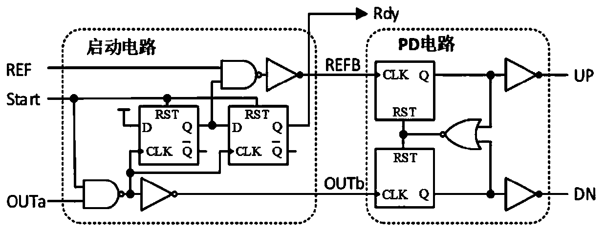
[0043] A resettable low-power fast phase detector circuit for a delay phase-locked loop according to an embodiment of the present invention includes: a start-up control circuit (module I) and a phase detection circuit (module II).

[0044] DLL generally includes four parts: phase detector, charge pump, loop filter and voltage-con...


PUM


Abstract

The invention discloses a delay phase-locked loop and a phase discriminator circuit thereof, and the delay phase-locked loop comprises a start control circuit which is used for adjusting the initial state of an input reference signal and a to-be-locked signal entering a phase discriminator, wherein the starting control circuit is of a resettable dynamic DFF structure; a phase detection circuit which is used for carrying out phase detection on the two input signals and outputting a narrow pulse width signal with phase information, wherein the two input signals are respectively obtained by a reference signal and a to-be-locked signal through a buffer, the phase detection circuit comprises two resettable dynamic DFFs with double CLKs, the reset ends of all the dynamic DFFs are connected to the RST. According to the phase discriminator circuit, phase discrimination is completed by using the dynamic DFF, and reset is triggered by the input signal, so that a reset path can be shortened, andthe phase detection speed is increased.

Description

technical field [0001] The invention belongs to the technical field of integrated circuits, in particular to a delay phase-locked loop and a phase detector circuit thereof. Background technique [0002] With the rapid development of integrated circuits, delay locked loop (Delay Locked Loop, DLL) has become a more commonly used on-chip clock generation technology, which uses negative feedback mechanism to obtain lower jitter with smaller power consumption and area clock. The phase detector (Phase Detector, PD) is an important part of the DLL. It is responsible for identifying the rising edges of the two input signals, generating two output control signals UP and DN with a certain pulse width, and the difference between the rising edges The value is proportional to the output pulse width. In order to avoid the situation of false locking, a start-up circuit is often added as an auxiliary. [0003] In a DLL, the traditional PD structure with a start-up circuit such as figure...

Claims


Application Information

Patent Timeline
IPC IPC(8): H03L7/08H03L7/093
CPCH03L7/0802H03L7/093
Inventor 佟星元吴进武
Owner XIAN UNIV OF POSTS & TELECOMM
Features
  • R&D
  • Intellectual Property
  • Life Sciences
  • Materials
  • Tech Scout
  • Unparalleled Data Quality
  • Higher Quality Content
  • 60% Fewer Hallucinations
Learn More