Edge chamfering device for furniture production

A chamfering device and edge technology, which is applied in the field of edge chamfering devices for furniture production, can solve the problems of inconvenient replacement of chamfering wheels and inability to perform chamfering, and achieve better chamfering effect, less shaking, and improved use effect of effect

Inactive Publication Date: 2020-03-13
佟春梅
View PDF1 Cites 2 Cited by
  • Summary
  • Abstract
  • Description
  • Claims
  • Application Information

AI Technical Summary

Problems solved by technology

A solid wood floor chamfering, polishing and deburring device in the above-mentioned patent has certain deficiencies: during use, the chamfering wheel is inconvenient to replace, resulting in uniform dimensions when chamfering edges, and wider edges are less It cannot be chamfered, and there are certain limitations in use. Therefore, it is urgent to design an edge chamfering device for furniture production to solve the above problems

Method used


Image

  • Edge chamfering device for furniture production
  • Edge chamfering device for furniture production
  • Edge chamfering device for furniture production

Examples


Embodiment 1

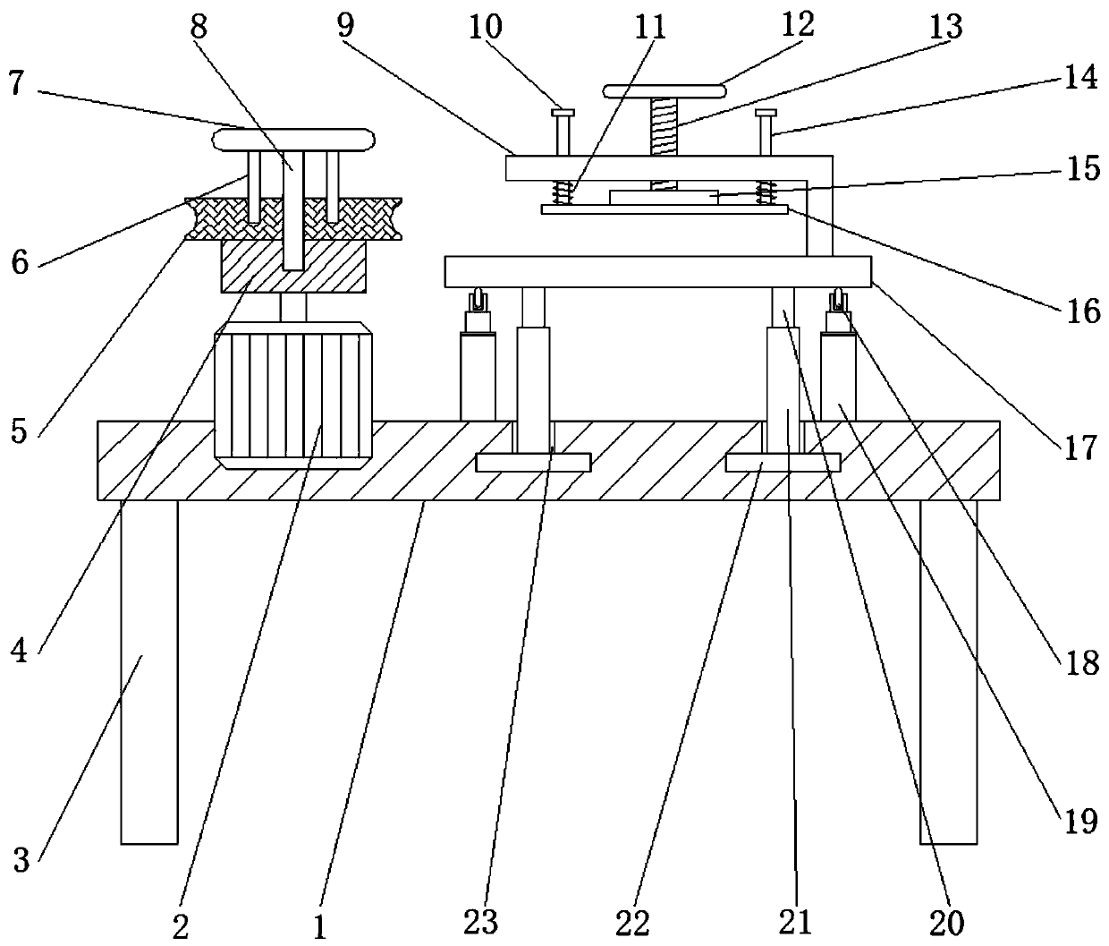
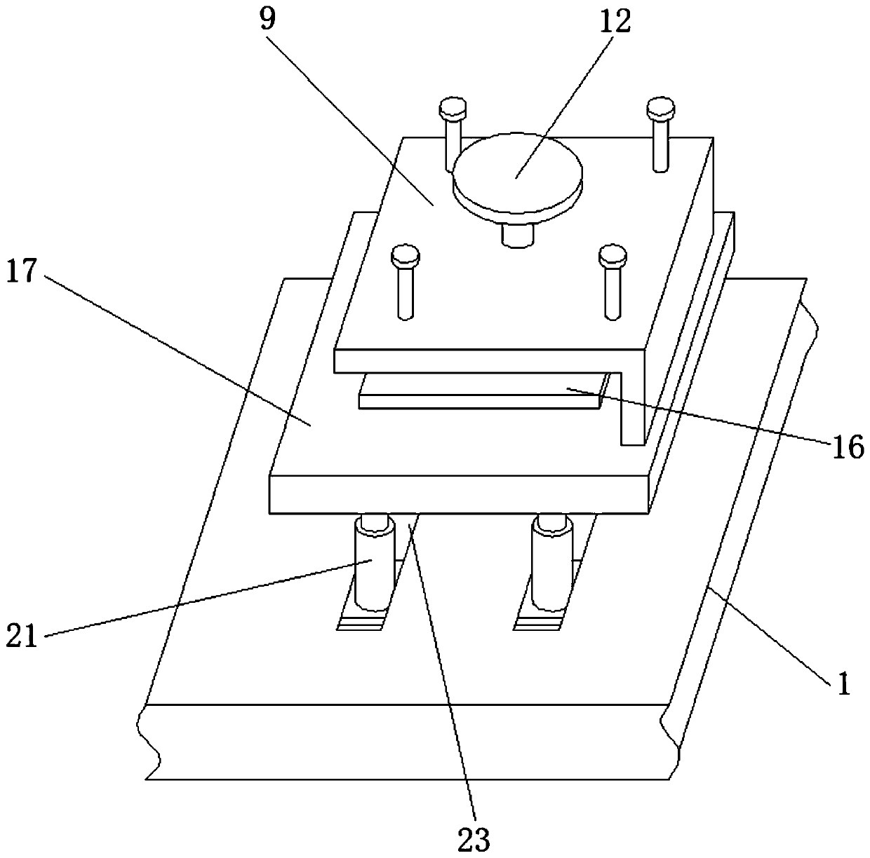
[0027] refer to Figure 1-2 , an edge chamfering device for furniture production, including a workbench 1, a mounting groove is opened on the top outer wall of the workbench 1, and a motor 2 is connected to the inner wall of the mounting groove through bolts, and a turntable 4 is arranged at one end of the output shaft of the motor 2 , and the top outer wall of the turntable 4 has a threaded groove, the inner wall of the threaded groove is threadedly connected with a threaded rod 8, the outer wall of the threaded rod 8 is sleeved with a chamfering wheel 5, and the top outer wall of the threaded rod 8 is welded with an adjustment wheel 7, and the adjustment The bottom outer wall of the wheel 7 is welded with a limit rod 6, the top outer wall of the chamfering wheel 5 has a limit groove, and the inner wall of the limit groove is plugged with the outer wall of the limit rod 6, and the four corners of the top outer wall of the workbench 1 are all There is a T-shaped slot 23, and t...

Embodiment 2

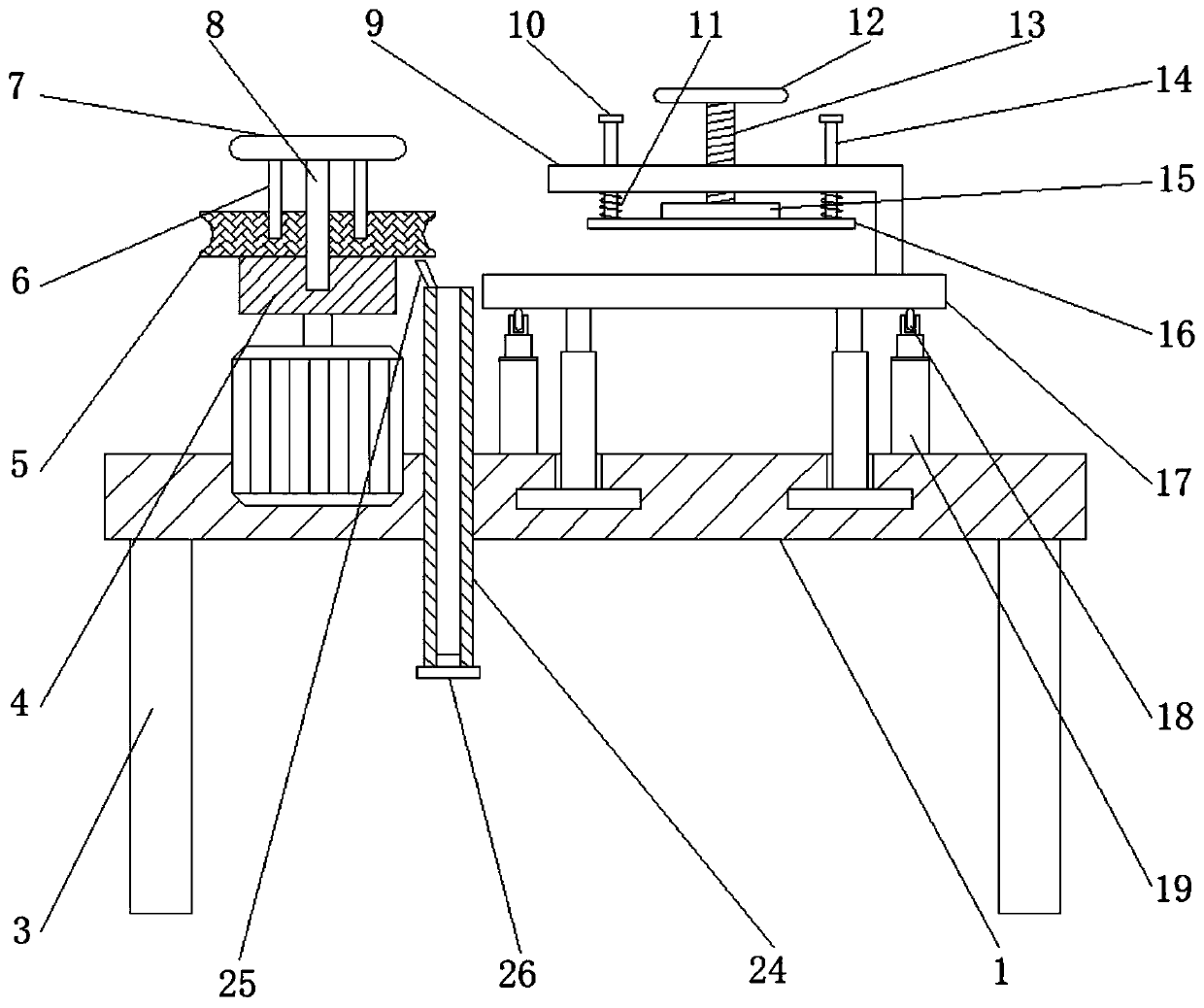
[0031] refer to image 3 , an edge chamfering device for furniture production. Compared with Embodiment 1, this embodiment also includes that the top outer wall of the workbench 1 is provided with an installation opening, and the inner wall of the installation opening is welded with a chip collecting bucket 24, and the chip collecting bucket The top outer wall of 24 is welded with a baffle plate 25 , and the bottom outer wall of the dust collection bucket 24 is clipped with a cover plate 26 .

[0032] Working principle: when in use, the chamfering chips will fall into the chip collecting bucket 24, and the baffle plate 25 on the chip collecting bucket 24 can well block the wood chips into the chip collecting bucket 24, when collected to a certain extent Finally, you can directly open the cover plate 26 to collect the sawdust, effectively avoiding the pollution of the workbench 1 by the sawdust produced by chamfering, and the use effect is better.


PUM


Abstract

The invention discloses an edge chamfering device for furniture production. The edge chamfering device for furniture production includes a workbench, a mounting groove is formed in the outer wall of the top of the workbench, the inner wall of the mounting groove is connected with a motor through bolts, a turntable is arranged at one end of an output shaft of the motor, a threaded groove is formedin the outer wall of the top of the turntable, the inner wall of the threaded groove is in threaded connection with a threaded rod, the outer wall of the threaded rod sleeves a chamfering wheel, an adjustment wheel is arranged on the outer wall of the top of the threaded rod, a limiting rod is welded to the outer wall of the bottom of the adjustment wheel, a limiting groove is formed in the outerwall of the top of the chamfering wheel, the inner wall of the limiting groove and the outer wall of the limiting rod are plugged in, and T-shaped grooves are formed at the four corners of the outer wall of the top of the workbench correspondingly. Replacement of the chamfering wheel is convenient, using has more flexibility, the effective limiting effect on a wood can be achieved so that the woodis less prone to shaking during chamfering, the chamfering effect is better, the chamfering position can be flexibly controlled, and the using effect of the device is further improved.

Description

technical field [0001] The invention relates to the technical field of furniture production, in particular to an edge chamfering device for furniture production. Background technique [0002] Furniture refers to the categories of utensils and facilities necessary for human beings to maintain normal life, engage in production practice and carry out social activities. Among them, solid wood furniture often needs to chamfer the edges of solid wood boards during processing to improve the safety during use. safety performance. [0003] After searching, the Chinese patent publication number is the patent of CN208179259U, discloses a kind of solid wood floor chamfering, polishing and deburring device, comprising a support platform, a cabinet, a support, the middle part of the lower end of the support platform is provided with the cabinet, and the upper end of the support platform Both sides are provided with slide rails, the upper end of the slide rail is provided with the bracket...

Claims


Application Information

Patent Timeline
Patent Type & Authority Applications(China)
IPC IPC(8): B27C5/02B27C5/06B27G3/00
CPCB27C5/02B27C5/06B27G3/00
Inventor 佟春梅
Owner 佟春梅
Why Eureka
Try Eureka