
Polarization reconfigurable method based on metasurface antenna

A linear polarization and metasurface technology, applied in the direction of antenna grounding switch structure connection, antenna, electrical components, etc., to achieve good side-fire characteristics, simple structure, and low profile

Active Publication Date: 2020-03-13
CHONGQING UNIV
View PDF3 Cites 6 Cited by
  • Summary
  • Abstract
  • Description
  • Claims
  • Application Information

AI Technical Summary

Problems solved by technology

At present, the reports on polarization reconfigurable antennas mainly focus on reconfigurability by mechanically rotating metasurfaces, and there are few reports on the method of realizing polarization reconfigurable metasurface antennas by means of electrical reconfiguration.

Method used


Image

  • Polarization reconfigurable method based on metasurface antenna
  • Polarization reconfigurable method based on metasurface antenna
  • Polarization reconfigurable method based on metasurface antenna

Examples


Embodiment Construction

[0029] The preferred embodiments of the present invention will be described in detail below with reference to the accompanying drawings.

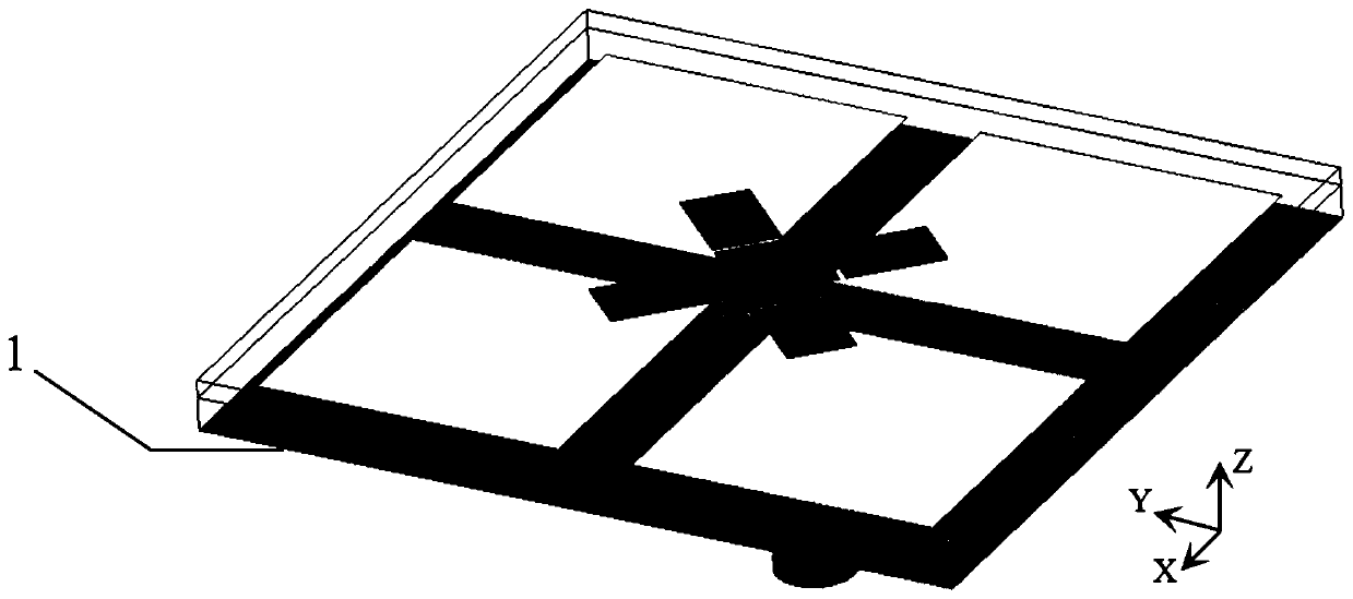
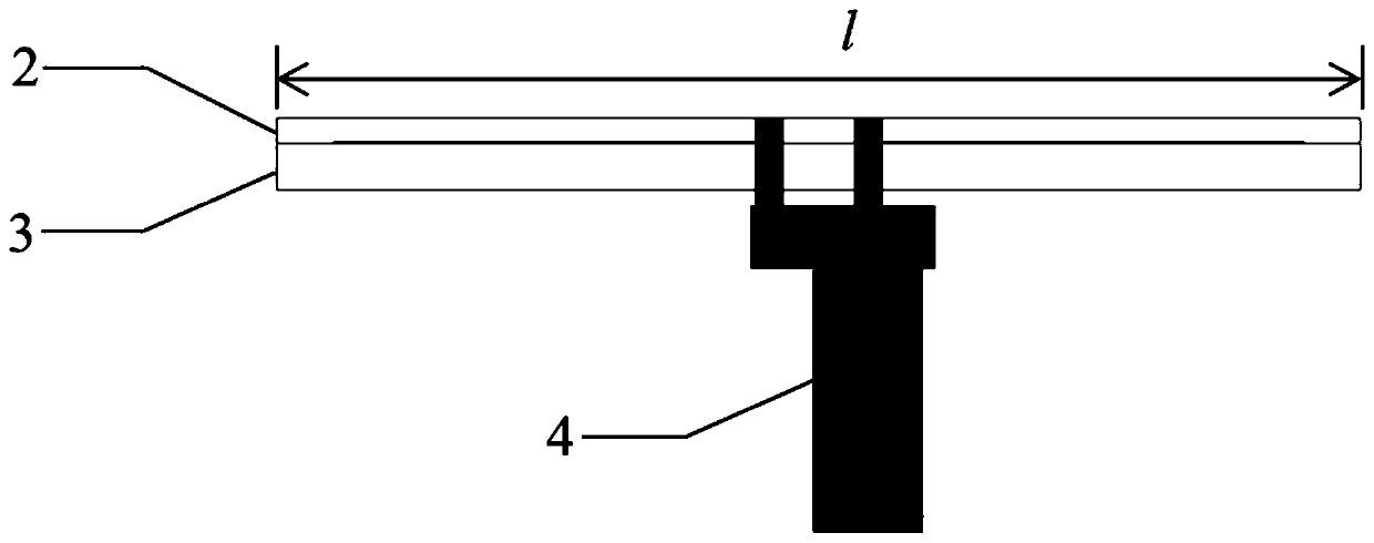
[0030] figure 1 It is the overall schematic diagram of the antenna of the present invention, such as figure 1 As shown, a low-profile, compact polarization-reconfigurable metasurface antenna described in the present invention mainly includes three parts: a metasurface structure, a polarization-reconfigurable feeding structure, and a metal floor.

[0031] Wherein, the metasurface structure is composed of four identical square subwavelength patches to form a 2×2 metasurface structure, and the spacing between the patch units is exactly the same;

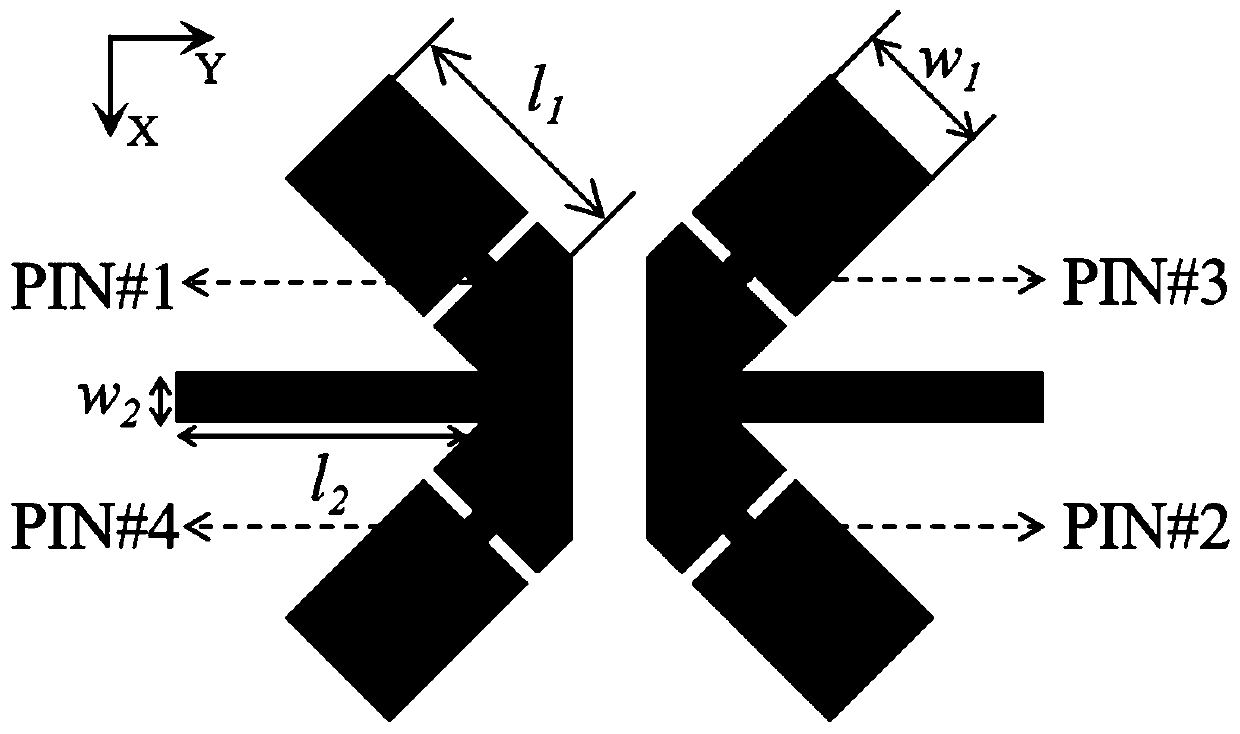
[0032] The polarization reconfigurable feeding part is composed of a double arrow dipole structure loaded with 4 PIN tubes (model is MA4GP907, the on state is equivalent to a resistance of 5.2Ω, and the off state is equivalent to a capacitance of 0.025pF) Composed of, PIN tube label see image 3 ,...


PUM


Abstract

The invention discloses a metasurface antenna polarization reconfigurable method capable of switching three states of linear polarization, left-hand circular polarization and right-hand circular polarization, and belongs to the technical field of antennas. The antenna comprises a metasurface, a polarization reconfigurable feed structure and a metal floor. The metasurface structure is composed of four square sub-wavelength patch units which are identical in size. The polarization reconfigurable feed structure is composed of a crossed dipole loaded with four PIN tubes and an arrow-shaped dipolejointly formed by two rectangular metal strips placed along the y axis, and a 50-ohm coaxial line is adopted to directly feed the polarized reconfigurable feed structure. According to the antenna, thefeed structure is converted into a corresponding L-shaped dipole form or a metal strip form along the y axis by controlling the conduction and cut-off states of the four PIN tubes, so that linear polarization, left-handed circular polarization or right-handed circular polarization is formed, and the rapid conversion among linear polarization, left-handed circular polarization or right-handed circular polarization can be realized. A metal floor is used for realizing the directional radiation of the antenna. According to the present invention, the metasurface structure is combined with the reconfigurable feed dipole structure, so that the electric reconfigurable design method of the metasurface antenna is realized; and the three-state polarization reconfigurable function of the metasurfaceantenna can be achieved by controlling the on-off of a few PIN switches of the polarization reconfigurable feed structure. Moreover, a novel L-shaped feed structure is provided for generating the circular polarization state, and meanwhile the antenna has the advantages of being compact, being low in profile, high in gain and low in cost, being easy to machine and the like.

Description

technical field [0001] The invention belongs to the technical field of antennas, and relates to a reconfigurable realization method of three states of linear polarization, left-handed circular polarization and right-handed circular polarization of a metasurface antenna. Background technique [0002] The polarization reconfigurable antenna can switch the polarization state between linear polarization and circular polarization, and improve system capacity by multiplexing the same channel and frequency spectrum, reducing polarization mismatch and channel interference. Compared with the reconfigurable antenna with the floor as the reflector and the electromagnetic dipole as the radiator, the polarized reconfigurable metasurface antenna has the advantage of low profile, and it has higher gain and wider bandwidth than the traditional patch antenna Advantages, without complex feed structure, avoiding the high loss problem of feed network. At present, the reports on polarization re...

Claims


Application Information

Patent Timeline
IPC IPC(8): H01Q1/50H01Q3/26H01Q3/34H01Q15/00
CPCH01Q1/50H01Q3/2658H01Q3/34H01Q15/0086
Inventor 李梅张哲豪唐明春
Owner CHONGQING UNIV
Learn More