
Annular liquid crystal dimming unit, aperture structure and electronic equipment

A technology of liquid crystal dimming and ring structure, which is applied in the field of optical devices and can solve problems such as the complexity of mechanical aperture structure design

Inactive Publication Date: 2020-03-17
黄剑鸣
View PDF10 Cites 1 Cited by
  • Summary
  • Abstract
  • Description
  • Claims
  • Application Information

AI Technical Summary

Problems solved by technology

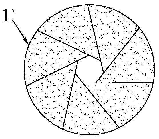
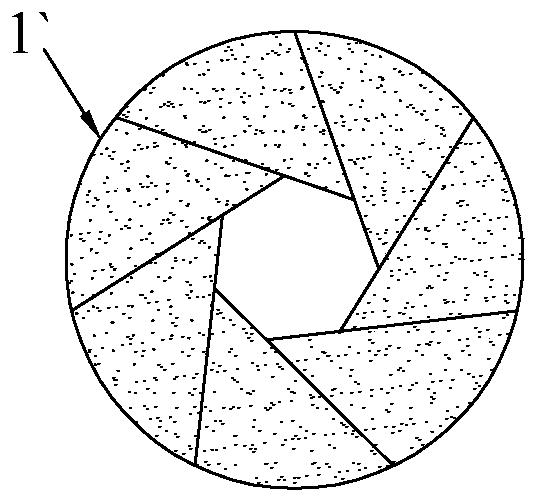
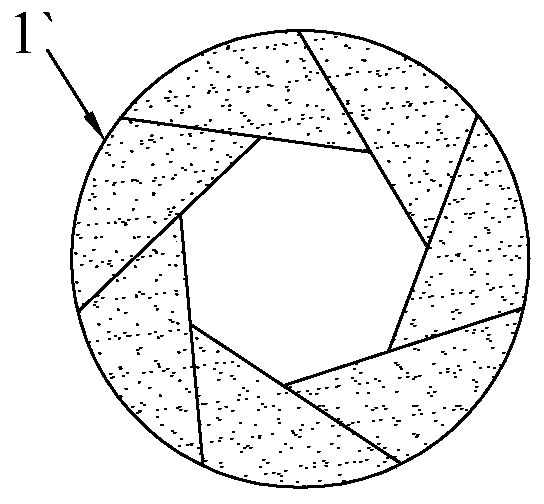
The existing mechanical aperture structure design is relatively complicated. Through long-term scientific research and social practice, the applicant has developed a non-mechanical aperture structure, which can completely replace the existing mechanical aperture structure.

Method used


Image

  • Annular liquid crystal dimming unit, aperture structure and electronic equipment
  • Annular liquid crystal dimming unit, aperture structure and electronic equipment
  • Annular liquid crystal dimming unit, aperture structure and electronic equipment

Examples


Embodiment Construction

[0032] Embodiments of the present invention will now be described with reference to the drawings, in which like reference numerals represent like elements.

[0033] like figure 2 and image 3 As shown, the electronic device 3 of the present invention includes a power supply, a lens 31 for optically capturing images, and a processing module 32 for processing images. The processing module 32 is electrically connected to the power supply. Generally, the power supply of the electronic device 3 is built-in or detachable. is installed in the housing of the processing module 32, the lens 31 includes an aperture structure 2 for controlling light flux, and the power supply is electrically connected with the power circuit in the aperture structure 2 (such as Image 6 As shown), the aperture structure 2 of the electronic device 3 of the present invention has a plurality of ring-shaped liquid crystal dimming units 1 that are independent of each other. When the light unit 1 is energized,...


PUM


Abstract

The invention discloses an annular liquid crystal dimming unit comprising a first polarizer, a first conducting film layer, a liquid crystal layer, a second conducting film layer, a glass layer and asecond polarizer which are all annular and are sequentially stacked to form a concentric annular structure. The first conducting film layer is of a light-transmitting and conductive structure. The first conducting film layer is electrically connected with a first wire; the second conducting film layer is of a light-transmitting and conductive structure, the second conducting film layer is electrically connected with a second wire, and when the first wire and the second wire are connected with a power supply, the liquid crystal layer is located in an electric field formed by the first conducting film layer and the second conducting film layer so that the annular liquid crystal dimming unit is light-transmitting, the light transmission disappears when the power supply is disconnected and thus the light flux can be adjusted. In addition, the invention further discloses an aperture structure with the dimming unit and electronic equipment.

Description

technical field [0001] The invention relates to an optical device, in particular to a dimming unit capable of reversibly adjusting light transmittance. Background technique [0002] At present, most dimming devices are made by coating on the glass surface. According to different reflection and light transmission requirements, films of different materials can be used to make light of a certain wavelength in the light reflect or transmit by the glass window. In order to achieve the purpose of transmission and reflection of light; once the structure of this coated glass is formed, its optical light transmission performance cannot be reversibly adjusted, and it cannot be adjusted from light transmission to opacity, or it cannot be changed from Light transmission is adjusted to light transmission. When using glass, it is often necessary to choose between light transmission and opacity. If it is fixed on one light performance, there is no need to use coated glass. In the case of ...

Claims


Application Information

Patent Timeline
Patent Type & Authority Applications(China)
IPC IPC(8): G02F1/1333G02F1/133G02F1/1335G03B9/02
CPCG02F1/1333G02F1/13306G02F1/133528G03B9/02
Inventor 范继良
Owner 黄剑鸣
Learn More