Printing device for packaging box production

A printing device and packaging box technology, applied in printing, printing machines, rotary printing machines, etc., can solve problems such as blurred printing, achieve the effects of preventing deviation, increasing friction, and improving convenience

Inactive Publication Date: 2020-03-20
株洲蓝海包装有限公司
View PDF16 Cites 3 Cited by
  • Summary
  • Abstract
  • Description
  • Claims
  • Application Information

AI Technical Summary

Problems solved by technology

A food packaging box printing device that is easy to fix in the above-mentioned patent has the following disadvantages: when the existing device is printing the packaging box, since a large amount of ink stains will adhere to the surface of the printing roller, it may be printed during printing. Printing can be blurred due to excessive ink smearing

Method used


Image

  • Printing device for packaging box production
  • Printing device for packaging box production
  • Printing device for packaging box production

Examples


Embodiment 1

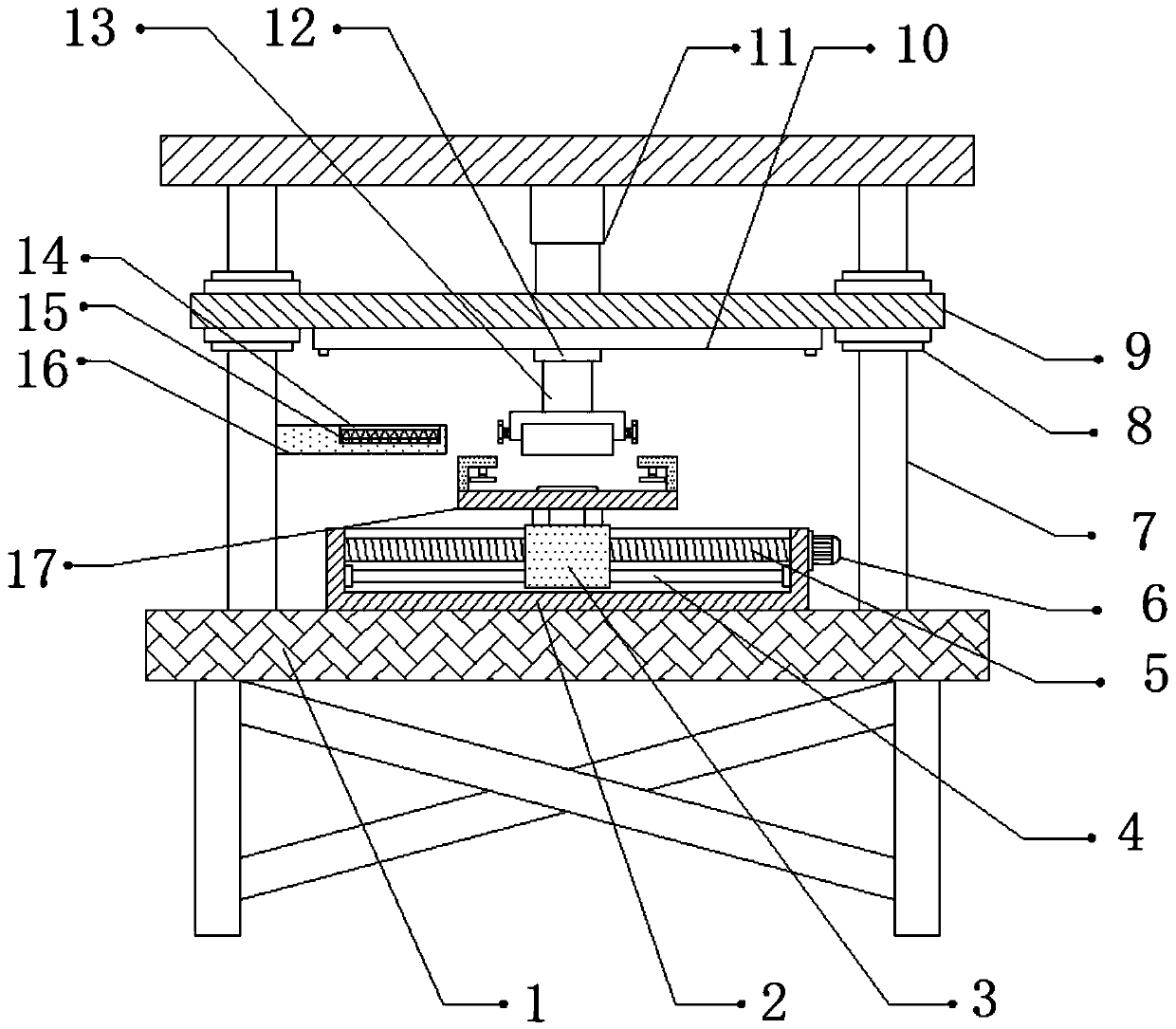
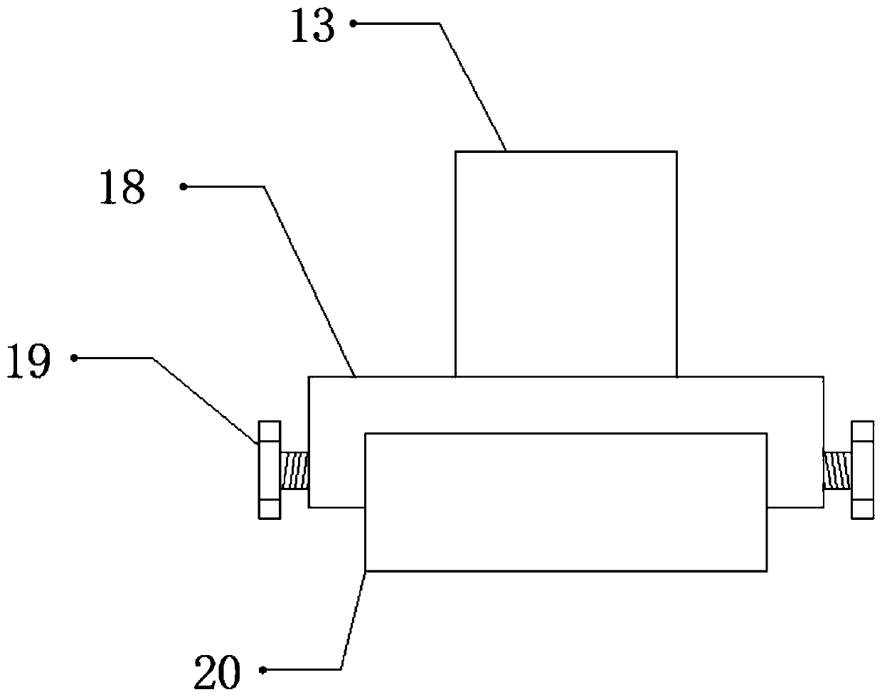
[0032] refer to Figure 1-3 , a printing device for packaging box production, comprising a fixing base 1, both sides of the top outer wall of the fixing base 1 are connected with fixing rods 7 by bolts, and the top outer walls of the two fixing rods 7 are connected with a top plate by bolts, and the top of the top plate The outer wall of the bottom is connected with the electric telescopic rod 11 by bolts, and the outer wall of the bottom of the electric telescopic rod 11 is connected with the fixed plate 9 by bolts, the outer wall of the bottom of the fixed plate 9 is connected with the electric slide rail 10 by bolts, and the inner wall of the electric slide rail 10 slides Slide block 12 is connected, the bottom outer wall of slide block 12 is connected with fixed shaft 13 by bolt, and the bottom outer wall of fixed shaft 13 is connected with fixed frame 18 by bolt, and the inner wall of fixed frame 18 is provided with template 20, and the two sides of fixed frame 18 The sid...

Embodiment 2

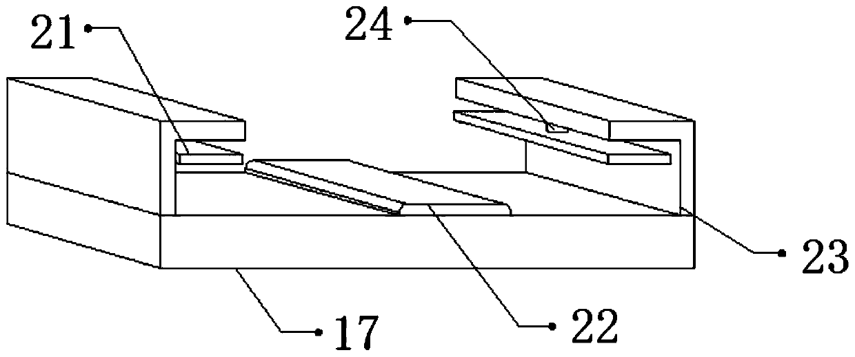
[0043] refer to Figure 4-5 , a printing device for packaging box production. Compared with Embodiment 1, the outer walls of the bottom of the two splints 21 are provided with a plurality of equidistant ribs 25, which can increase the distance between the splint 21 and the packaging box. The frictional force prevents the movement between the packaging box and the splint 21 due to vibration, thereby causing deviation to the printing of the packaging box.

[0044] Working principle: when in use, place the packaging box that needs to be printed on the support plate 17, start the hydraulic rod 24, and the hydraulic rod 24 will drive the splint 21 to move, so that the splint 21 fixes the two sides of the packaging box. The rib 25 can increase the friction between the splint 21 and the packing box, prevent the packing box from moving between the splint 21 due to vibration, thereby causing deviation to the printing of the packing box, and the raised plate 22 highlights the part of th...


PUM


Abstract

The invention discloses a printing device for packaging box production. The device comprises a fixed seat, fixing rods are fixed to the two sides of the outer wall of the top of the fixing base respectively, a top plate is fixed to the outer walls of the tops of the two fixing rods correspondingly, an electric telescopic rod is fixed to the outer wall of the bottom of the top plate, a fixing plateis fixed to the outer wall of the bottom of the electric telescopic rod, an electric sliding rail is fixed to the outer wall of the bottom of the fixing plate, a sliding block is slidably connected to the inner wall of the electric sliding rail, a fixing shaft is fixed to the outer wall of the bottom of the sliding block, a fixing frame is fixed to the outer wall of the bottom of the fixing shaft, and a template is arranged on the inner wall of the fixing frame. According to the invention, influence of blurred printed handwriting on packaging box production can be prevented, the bottom of thetemplate can be prevented from being abraded to influence printing of the packaging box, deviation of printing of the device on the packaging box can be prevented, and deviation of printing of the packaging box caused by movement between the packaging box and the clamping due to vibration can be prevented.

Description

technical field [0001] The invention relates to the technical field of packaging box production, in particular to a printing device for packaging box production. Background technique [0002] Food packaging is an integral part of food commodities and one of the main projects in the food industry process. It protects food and prevents damage from biological, chemical and physical external factors during the circulation of food from the factory to the hands of consumers. , it can also have the function of maintaining the stable quality of the food itself. It is convenient for the consumption of food, and it first shows the appearance of the food and attracts consumption. It has value other than material cost. In the production process of food packaging bags, generally Various patterns, advertisements and instructions are printed on the surface of the bag, which has achieved the effect of publicity and display. [0003] After retrieval, the Chinese Patent Grant No. is the pate...

Claims


Application Information

Patent Timeline
Patent Type & Authority Applications(China)
IPC IPC(8): B41F17/24B41F31/02
CPCB41F17/24B41F31/02
Inventor 肖颖喆熊翠军张艳华
Owner 株洲蓝海包装有限公司
Why Eureka
Try Eureka