Pile bottom grouting cavity and use method, and poured pile body and construction method of poured pile body

A technology of grouting cavity and cast-in-place pile, which is applied in the direction of sheet pile wall, foundation structure engineering, building, etc. It can solve problems such as grouting pipe blockage, improve the bearing capacity of pile ends, ensure the effect of compaction, and ensure the smooth flow of pipelines Effect

Active Publication Date: 2020-03-20
高永光 +1
View PDF6 Cites 7 Cited by
  • Summary
  • Abstract
  • Description
  • Claims
  • Application Information

AI Technical Summary

Problems solved by technology

[0004] Therefore, the present invention aims to provide a grouting cavity at the bottom of the pile and a method of use thereof and a construction method of a cast-in-place pile body and a cast-in-place pile body, so as to solve the problem that mixtures such as soil, silt, and stones will pass through the grouting cavity at the bottom of the pile in the prior art. into the grouting pipe, resulting in the problem of clogging of the grouting pipe

Method used


Image

  • Pile bottom grouting cavity and use method, and poured pile body and construction method of poured pile body
  • Pile bottom grouting cavity and use method, and poured pile body and construction method of poured pile body
  • Pile bottom grouting cavity and use method, and poured pile body and construction method of poured pile body

Examples


Embodiment 1

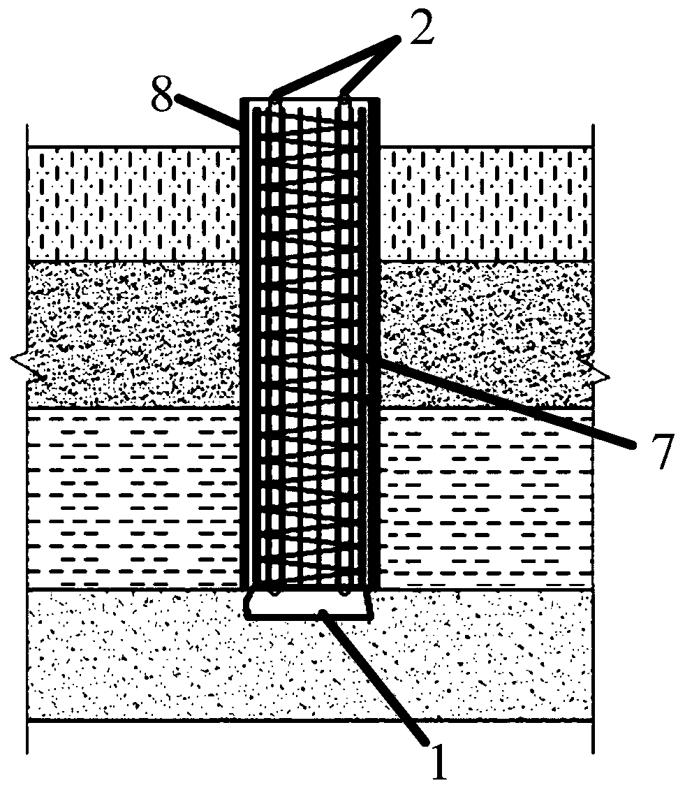
[0070] A kind of cast-in-place pile body provided in this embodiment, such as Figure 6 shown, including:

[0071] Pile bottom grouting cavity;

[0072] Reinforcement cage 7 is connected with the grouting cavity at the bottom of the pile, and the grouting pipe 2 is fixedly connected with the reinforcement cage 7 by binding. The reinforcement cage 7 is also fixed with a pile side grouting pipe 10. The pile The grouting hole of the side grouting pipe 10 is arranged at a position close to the grouting capsule 1, grouting towards the pile side formation;

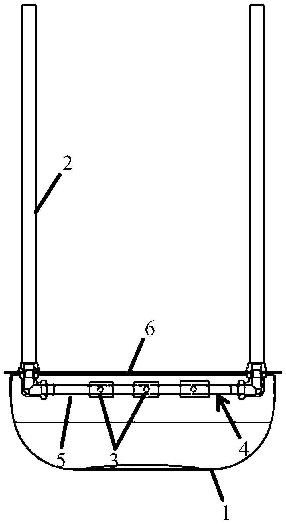
[0073] The pile bottom grouting cavity in this application, such as figure 1 shown, which includes:

[0074] The grouting capsule 1 is made of rubber, and has an expanded state filled with grout to carry the pile body, and a contracted state with a hollow interior;

[0075] The grouting pipe 2 communicates with the inner cavity of the grouting capsule 1, and injects grout into the grouting capsule 1. The grouting tube 2 has ...

Embodiment 2

[0096] The difference between this embodiment and embodiment 1 is that the construction method of the cast-in-situ pile body comprises the following steps:

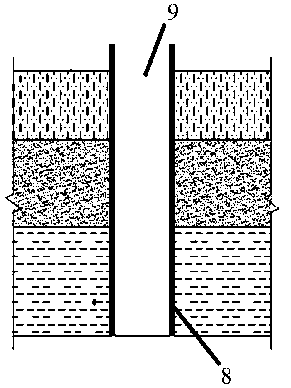
[0097] S1, forming a hole by artificial wall-retaining method to form a hole 9 with an artificial wall;

[0098] S2, sinking the reinforcement cage 7 with the pile bottom grouting cavity installed at the lower end to the bottom of the hole 9;

[0099] S3, pouring concrete into the hole 9, so that the reinforcement cage 7 and the inner cavity wall of the hole 9 are fixed together;

[0100] S4, injecting grout into the grouting capsule 1 to form a pile bottom expansion head;

[0101] The following problems can be effectively prevented by using the artificial retaining wall to form a hole with the cast-in-place pile body: when the cast-in-situ pile body is formed with a mud retaining wall, the reinforcement cage with the fixing plate 6 is stuck in the drilled hole when the reinforcement cage is lowered to the bottom of the ...


PUM


Abstract

Disclosed in the present invention are a pile bottom grouting cavity and a use method thereof, and a poured pile body and a construction method of the poured pile body. The pile bottom grouting cavitycomprises: a grouting capsule having an expansion state in which the interior thereof is filled with slurry to bear a pile body and a contraction state in which the interior thereof is empty; a grouting tube in communication with the inner chamber of the grouting capsule so as to grout the grouting capsule; and a check valve provided at a communication position between the grouting tube and the grouting capsule so as to block plugs within the grouting capsule from entering the grouting tube. The present invention avoids the problem in the prior art that the grouting tube is blocked due to a mixture of mud, sediment and the like in the grouting capsule entering the grouting tube.

Description

technical field [0001] The invention relates to the technical field of ground foundations, in particular to a grouting cavity at the bottom of a pile, a method for using it, a cast-in-place pile body and a construction method for the cast-in-place pile body. Background technique [0002] At present, in the foundation field, open grouting is generally used in the grouting after pouring piles. However, the open grouting has the problems of low controllability of the grout injection area, the formation of the enlarged head of the pile, the compaction effect on the surrounding strata, and the small increase in the bearing capacity of the pile. [0003] In order to solve the problem of open grouting. In the prior art, a grouting device for cast-in-situ piles with a grouting capsule is disclosed, which includes a grouting pipe, a steel floor, a grouting interface, and a grouting capsule, and the grouting interface extends above and below the steel floor. The upper part of the gr...

Claims


Application Information

Patent Timeline
Patent Type & Authority Applications(China)
IPC IPC(8): E02D5/62E02D15/04
CPCE02D5/62E02D15/04E02D2250/0023
Inventor 高永光高云飞
Owner 高永光
Why Eureka
Try Eureka