Check patentability & draft patents in minutes with Patsnap Eureka AI!

A method for measuring positioning error of machine tool workbench

A technology of positioning error and measurement method, which is used in measurement/indication equipment, manufacturing tools, metal processing equipment, etc., can solve the problems of machine tool processing accuracy, poor real-time performance, and inability to compensate for tool fluctuations in time, to improve processing quality and Efficiency and the effect of real-time compensation

Active Publication Date: 2021-04-20
XY HUST ADVANCED MFG ENG RES INST +3
View PDF11 Cites 0 Cited by
  • Summary
  • Abstract
  • Description
  • Claims
  • Application Information

AI Technical Summary

Problems solved by technology
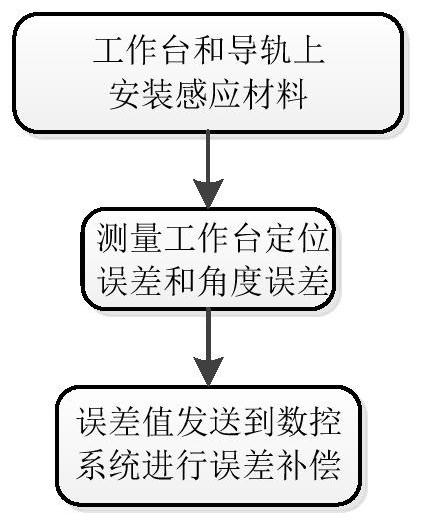
[0003] However, this measurement method is inefficient and has high requirements for the operator. The measurement is generally carried out when the machine tool is not processed, so the real-time performance of the measurement is poor, and the tool fluctuations during the processing cannot be compensated in time. , so that the machining accuracy of the machine tool is affected

Method used


Image

  • A method for measuring positioning error of machine tool workbench
  • A method for measuring positioning error of machine tool workbench
  • A method for measuring positioning error of machine tool workbench

Examples


Embodiment Construction

[0028] In order to make the purpose, features and advantages of the present invention more obvious and understandable, the technical solutions in the embodiments of the present invention will be clearly and completely described below in conjunction with the accompanying drawings in the embodiments of the present invention. Obviously, the following The described embodiments are only some, not all, embodiments of the present invention. Based on the embodiments of the present invention, all other embodiments obtained by persons of ordinary skill in the art without making creative efforts belong to the protection scope of the present invention.

[0029] The technical solutions of the present invention will be further described below in conjunction with the accompanying drawings and through specific implementation methods.

[0030] In the description of the present invention, it should be understood that the orientations or positional relationships indicated by the terms "upper", "...


PUM


Abstract

The invention discloses a method for measuring the positioning error of a machine tool workbench. The actual moving distance of the workbench in the guide rail of the machine tool and the contact stress value on both sides of the workbench are acquired through an induction device; Positioning error and yaw error; transmit the positioning error and yaw error to the CNC control module to complete the supplement of the collective error of the machine tool. Advantages: the present invention obtains the position error and yaw angle error of the workbench during actual processing through real-time measurement, and the measurement results directly reflect the final position and yaw angle of the workbench when it runs along each axis. According to the actual measurement results, it is fed back to the CNC system to maximize the real-time compensation of the CNC system, thereby improving the processing quality and efficiency.

Description

technical field [0001] The invention relates to a positioning error measurement method of a machine tool workbench, belonging to the technical field of geometric error measurement and compensation of machine tools. Background technique [0002] In CNC machining, relying on the screw drive to drive the spindle and the table to move is the current method used. In order to improve the positioning accuracy of the worktable movement, accurate measurement of the displacement and yaw angle of the worktable movement is a prerequisite for error compensation. Since the lead screw is a slender rod, it will be thermally elongated due to the influence of temperature, and the movement of the worktable depends on the rotation of the lead screw to transmit motion and power, which will affect the moving position of the worktable. At present, the method adopted is to detect the positioning accuracy of the worktable with the help of measuring equipment. The measured data comes from the laser ...

Claims


Application Information

Patent Timeline
Patent Type & Authority Patents(China)
IPC IPC(8): B23Q17/00
CPCB23Q17/00
Inventor 刘宏伟杨锐向华李波陈国华姜涛武艳苗
Owner XY HUST ADVANCED MFG ENG RES INST
Features
  • R&D
  • Intellectual Property
  • Life Sciences
  • Materials
  • Tech Scout
  • Unparalleled Data Quality
  • Higher Quality Content
  • 60% Fewer Hallucinations
Learn More