Novel wide-range high-frequency direct-current conversion device

A DC conversion and high-frequency conversion technology, applied in the output power conversion device, the conversion of DC power input to DC power output, and the adjustment of electrical variables, etc. question

Active Publication Date: 2020-03-24
NO 719 RES INST CHINA SHIPBUILDING IND
View PDF3 Cites 2 Cited by
  • Summary
  • Abstract
  • Description
  • Claims
  • Application Information

AI Technical Summary

Problems solved by technology

However, the Buck circuit is mainly used in step-down applications, and the Boost circuit is mainly used in step-up applications, both of which have their own special application scenarios and are not suitable for wide voltage ranges.
Cascading the Buck and Boost circuits can effectively adapt to a wider voltage range, but the two-stage conversion leads to a decrease in efficiency. At the same time, in order to improve the output performance of the converter, the filter inductance and capacitance are large
In order to adapt to high-power applications, usually multiple Buck and Boost circuits can be connected in parallel. At the same time, the number of inductors used will also double, and the volume and weight will increase significantly.
Moreover, since the conventional Buck and Boost circuits cannot realize soft switching, the circuit efficiency is low, and the EMI characteristics are poor. In order to improve the characteristics, a lot of EMI filtering measures must be added.
[0004] Therefore, in the state of the art, how to adapt the DC conversion device to a wide range of input and output voltages, while ensuring high efficiency and high density, and how to improve the safety of the DC power grid have yet to be resolved.

Method used


Image

  • Novel wide-range high-frequency direct-current conversion device
  • Novel wide-range high-frequency direct-current conversion device
  • Novel wide-range high-frequency direct-current conversion device

Examples


Embodiment Construction

[0062] The present invention will be further described below in conjunction with the accompanying drawings and specific embodiments.

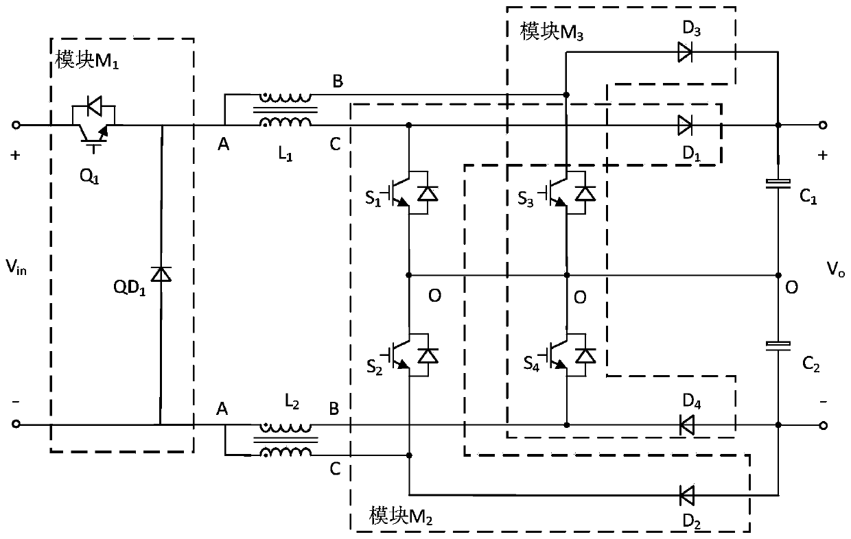
[0063] figure 1 It is a main circuit diagram of a wide-range high-frequency DC conversion device according to an embodiment of the present invention. Such as figure 1 As shown, the wide-range high-frequency DC conversion device in this embodiment includes a Buck module M 1 , 2 coupled inductors L 1 , L 2 , 2 three-level Boost modules M 2 , M 3 , and 2 support capacitors C 1 、C 2 .

[0064] from figure 1 It can be seen that the Buck module M 1 Including switching tube Q 1 and diode QD 1 . DC input V in The anode of the switch tube Q is connected to 1 collector of the DC input V in The cathode of the diode QD is connected to 1 anode of the diode QD 1 The cathode and switching tube Q 1 connected to the launch stage.

[0065] Each coupled inductor includes three connection terminals A, B, C, and a diode QD 1 The cathode and the...


PUM


Abstract

The invention discloses a novel wide-range high-frequency direct-current conversion device. The direct-current conversion device comprises a Buck module M1, a first coupling inductor L1, a second coupling inductor L2, a first three-level Boost module M2, a second three-level Boost module M3, a first supporting capacitor C1 and a second supporting capacitor C2. According to the Boost circuit, an interleaved three-level control strategy is adopted, the inductive current frequency is increased to four times of the switching frequency, soft switching of a switching device and a diode can be achieved through coupling inductance leakage inductance, the device loss is reduced, and the EMI characteristic is improved. Besides, the front-stage Buck circuit and the rear-stage Boost circuit are cascaded so that the application range of the input and output voltage can be broadened and short-circuit current-limiting operation of the output side can be realized. Meanwhile, the pre-stage Buck circuitcan realize a soft power-on function, an additional soft power-on circuit is not needed, and the power density of the device is further improved.

Description

technical field [0001] The invention relates to a novel wide-range high-frequency DC conversion device, which belongs to the field of power electronic conversion, and is particularly suitable for wide-range input and output, high power density, high-efficiency and high-power conversion, and applications requiring short-circuit current limiting. Background technique [0002] In the application fields of new energy microgrid, DC distribution network and all-electric ships, the energy systems in the power network are usually wind turbines, solar cells and energy storage systems. The output DC voltage of these energy systems usually has a wide range and large fluctuations. DC power loads usually require a stable DC voltage, and the DC voltages required by different DC loads are also different. Therefore, a DC conversion device suitable for a wide input and output range is required. At the same time, due to the difficulty in protection of the DC power grid, it is difficult to cut...

Claims


Application Information

Patent Timeline
Patent Type & Authority Applications(China)
IPC IPC(8): H02M3/158
CPCH02M3/1582
Inventor 李锐张鹏程金翔吴浩伟汪文涛蔡凯姜波张正卿邢贺鹏孔祥伟张炜龙金惠锋李鹏帅骁睿陈涛罗伟耿攀
Owner NO 719 RES INST CHINA SHIPBUILDING IND
Why Eureka
Try Eureka