Guide plate molding machining device and using method thereof

A guide plate and processing device technology, which is applied to manufacturing tools, casting and forming equipment, metal processing equipment, etc., can solve the problems of insufficient product machining allowance, consumption of cutting nozzles, shrinking working surface, etc., so as to reduce the cost of auxiliary materials and labor. , The effect of improving work efficiency and sufficient machining allowance

Inactive Publication Date: 2020-03-27
HENGYANG HONGYU MACHINERY MANFUACTURING CO LTD
View PDF5 Cites 2 Cited by
  • Summary
  • Abstract
  • Description
  • Claims
  • Application Information

AI Technical Summary

Problems solved by technology

[0003] At present, most of the guide plate casting technology for continuous rolling mill perforation in the market uses quick-drying sand at the runner, insulation sand around the riser, and resin sand molding process around the guide plate. After the product is poured out of the box, the riser and runner And around the dovetail of the guide plate, it is easy to sinter, stick to sand, sink and deform the working surface, resulting in insufficient processing allowance of the product and high strength when cutting the product. It is necessary to clean the sand formation around the riser and runner of the product with plasma. For cutting, product improvement consumes a lot of cutting nozzles and high labor costs. Therefore, in view of the above problems, a guide plate molding process and its use method are proposed

Method used


Image

  • Guide plate molding machining device and using method thereof
  • Guide plate molding machining device and using method thereof
  • Guide plate molding machining device and using method thereof

Examples


Embodiment

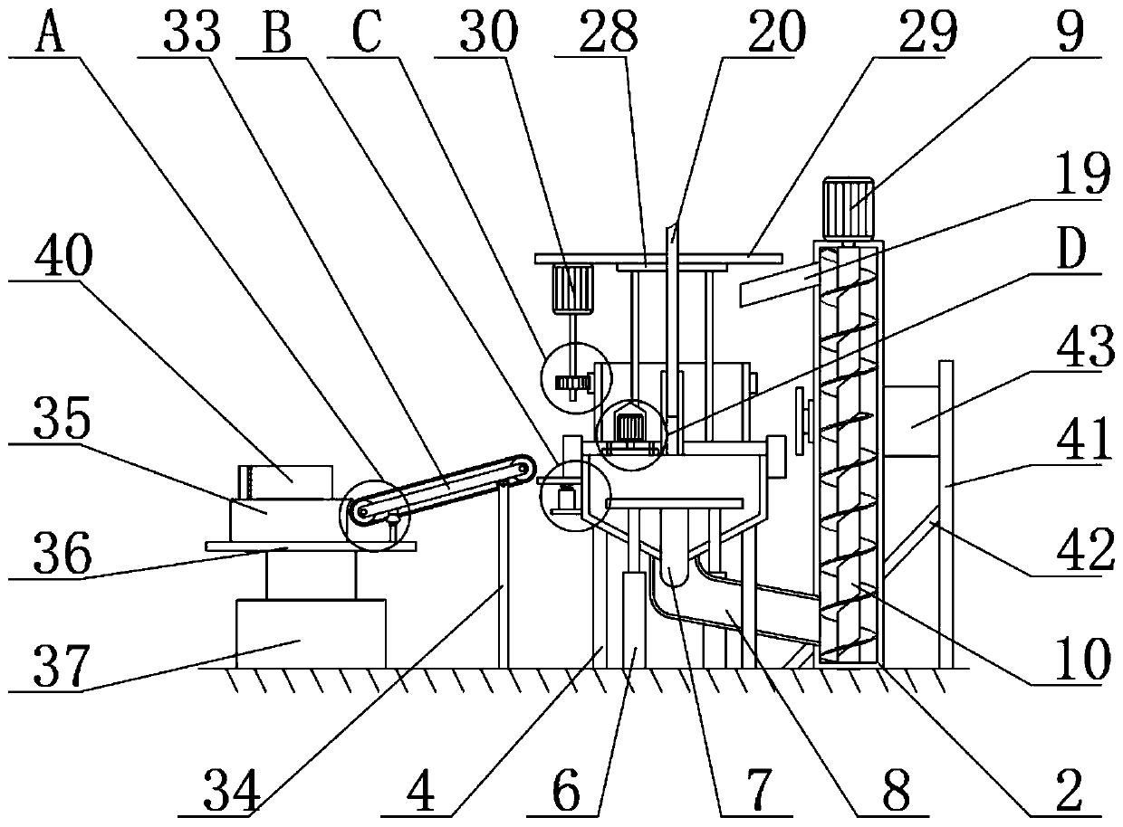
[0033] Example: see Figure 1-10 , the present invention provides a technical solution:

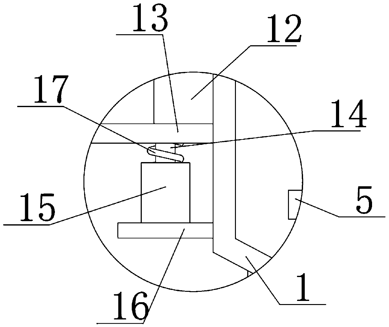
[0034] A guide plate molding process and its use method, comprising a forming box 1, a return cylinder 2 and a collecting plate 35, the bottom end surface of the forming box 1 is fixedly connected with a support leg 4, and the bottom end of the support leg 4 is fixed to the ground connection, the inner side of the forming box 1 is provided with a placement plate 5, the setting of the placement plate 5 is convenient for taking out the material, the bottom end surface of the placement plate 5 is fixedly connected with the first hydraulic rod 6, and the first hydraulic rod 6 It runs through the forming box 1, and the first hydraulic rod 6 is slidingly connected with the forming box 1, the bottom end surface of the first hydraulic rod 6 is fixedly connected with the ground, and the bottom end surface of the placement plate 5 is fixedly connected with a blocking block 7, so The blocking block...


PUM


Abstract

The invention relates to the technical field of continuous mills, in particular to a guide plate molding machining device and a using method thereof. The guide plate molding machining device comprisesa forming box, a material return barrel and a collecting plate; supporting legs are fixedly connected to the bottom end surface of the forming box, and the bottom ends of the supporting legs are fixedly connected with the ground; the inner side of the forming box is provided with a placement plate, and the bottom end surface of the placement plate is fixedly connected with a first hydraulic rod;the first hydraulic rod penetrates through the forming box and is slidably connected with the forming box, and the bottom end surface of the first hydraulic rod is fixedly connected with the ground; the bottom end surface of the placement plate is fixedly connected with a plugging block, and the plugging block is slidably connected with the forming box; and the bottom end surface of the forming box communicates with a recycling pipe, and the recycling pipe communicates with the material return barrel. According to the guide plate molding machining device and the using method thereof, only resin sand is adopted for filling, after being subjected to pouring and taken out of the box, a product is smooth in surface and free of sintering, sand burning, shrinkage depression and other defects, inaddition, the machining allowance is enough, the working efficiency is greatly improved, and the accessory cost and the manpower cost are reduced.

Description

technical field [0001] The invention relates to the technical field of continuous rolling mills, in particular to a molding process of a guide plate and a method for using the same. Background technique [0002] In recent years, China has imported dozens of the world's most advanced continuous rolling mills from SMS AG of Germany, Mitsubishi of Japan and Danieli of Italy. After digestion, transformation and innovation, China has also begun to independently integrate modern continuous rolling mills Several sets were put into production. With the introduction of high-power frequency conversion devices for the main drive of the rolling mill and the multi-functional perfection of the hydraulic pressing system for more than 20 years, the continuous rolling mill uses the guide plate when it is needed in the piercing work. Therefore, a guide plate molding process and its There is a growing demand for methods of use. [0003] At present, most of the guide plate casting technology ...

Claims


Application Information

Patent Timeline
Patent Type & Authority Applications(China)
IPC IPC(8): B22C9/04B22D29/06B22C5/00
CPCB22C5/00B22C9/04B22D29/06
Inventor 欧阳淑兵石志军付清华宁波何泽成
Owner HENGYANG HONGYU MACHINERY MANFUACTURING CO LTD
Why Eureka
Try Eureka