
Welding gun structure of electric spark bead weld repairing machine

A repairing machine and electric spark technology, applied in arc welding equipment, welding rod characteristics, welding equipment and other directions, can solve the problems of carbon brush consumption and damage, welding torch can not work, wire ends fall off, etc. The effect of insulation

Pending Publication Date: 2020-03-27
安徽华生机电集团有限公司
View PDF1 Cites 0 Cited by
  • Summary
  • Abstract
  • Description
  • Claims
  • Application Information

AI Technical Summary

Problems solved by technology

[0003] In the existing cold welding technology, the following obvious defects often occur in the welding torch during work: 1. Metal spatter particles are generated when the welding wire and the workpiece are surfacing, and then fall into between the carbon brush structure and the welding wire chuck, causing There is a gap between the carbon brush structure and the welding wire chuck, which causes vibration between the carbon brush structure and the welding wire chuck to generate electric spark and electric corrosion; 2. The electric spark and electric corrosion will continuously damage the carbon brush body, resulting in rapid consumption and damage of the carbon brush. At the same time, the vibration of the carbon brush structure will continue to pull the wire, which will easily cause the wire end to fall off, and eventually cause the welding torch to fail to work, affect normal use, and reduce service efficiency and life.

Method used


Image

  • Welding gun structure of electric spark bead weld repairing machine
  • Welding gun structure of electric spark bead weld repairing machine
  • Welding gun structure of electric spark bead weld repairing machine

Examples


Embodiment Construction

[0030] The following will clearly and completely describe the technical solutions in the embodiments of the present invention with reference to the accompanying drawings in the embodiments of the present invention. Obviously, the described embodiments are only some, not all, embodiments of the present invention. Based on the embodiments of the present invention, all other embodiments obtained by persons of ordinary skill in the art without making creative efforts belong to the protection scope of the present invention.

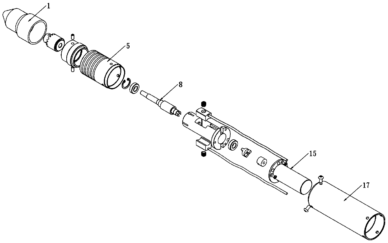
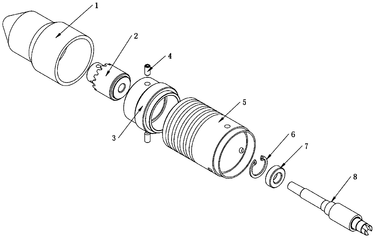
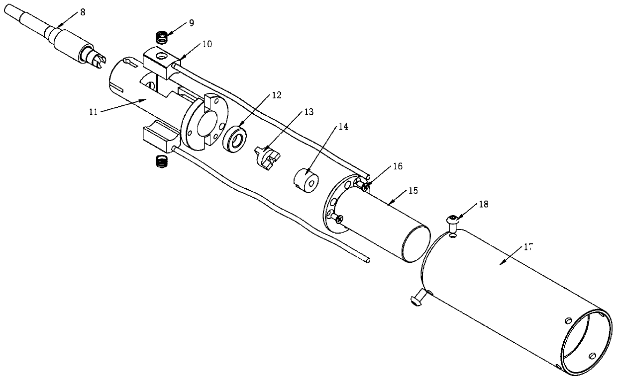
[0031] see Figure 1-11 , the present invention provides a technical solution:

[0032] A welding torch structure of an electric spark surfacing repair machine, comprising: a welding torch front cover 1, a welding wire chuck 2, a threaded sleeve 3, a set screw 4, a jacket 5, a retaining spring 6, a bearing 7, a spindle assembly 8, a spring 9, Carbon brush assembly 10, inner sleeve 11, bearing 2 12, insulating coupling 13, motor coupling 14, geared motor assem...


PUM

PropertyMeasurementUnit
Lengthaaaaaaaaaa

Abstract

The invention discloses a welding gun structure of an electric spark bead weld repairing machine. The welding gun structure comprises a welding gun front cover, a welding wire chuck, a threaded sleeve, a set screw, an outer sleeve, a clamping spring, a first bearing, a main shaft assembly, a spring, a carbon brush assembly, an inner sleeve, a second bearing, an insulating coupler, a motor coupler,a gear motor assembly, a first screw, a handheld gun sleeve and a second screw. According to the welding gun structure, electric spark and electric corrosion are not prone to be generated by a carbonbrush assembly structure, the structure of a carbon brush body becomes small, a carbon brush lead wire does not need to be exposed outside, and a welding gun can be used stably and safely; a carbon brush is installed on the inner side of the outer sleeve, the carbon brush is tightly attached to the outer side of a main shaft assembly brass sleeve under the action of an elastic force of a spring,so as to form reliable electric conduction, and the outer sleeve, the threaded sleeve and the insulating coupler are all made of non-metallic materials, thereby improving the heat insulation and insulation effects of the welding gun; and the carbon brush assembly is sealed in the gun body, and external splashing metal particles cannot enter the gun body.

Description

technical field [0001] The invention relates to the field of technical welding devices, in particular to an electric spark surfacing repair machine welding torch structure. Background technique [0002] Electric spark surfacing repair machine welding gun is an important electromechanical equipment, such as a water-cooled electric spark repair machine welding gun with application number 201720039157.4, including welding wire chuck, carbon brush, carbon brush fixed body, gun shell, tail flange, water cooling body , the first water pipe, the second water pipe, the motor, the cable clamp block, the link cable, the water circulation chamber, the gun shaft, the cable connection piece, the spring insulating frame, the spring and the bearing, and the carbon brush fixed body is arranged at the front end of the water cooling body , the spring is arranged at the rear end of the carbon brush fixed body, and the carbon brush is embedded in the front end of the carbon brush fixed body. T...

Claims


Application Information

Patent Timeline
IPC IPC(8): B23K9/28B23K9/04B23K9/32
CPCB23K9/04B23K9/28B23K9/32
Inventor 许克生
Owner 安徽华生机电集团有限公司
Learn More