Three-chuck laser pipe cutter device

A technology of laser cutting and laser cutting head, which is applied in the direction of auxiliary devices, laser welding equipment, tubular objects, etc., can solve the problem of the length of remaining tailings, etc., and achieve the effect of ensuring cutting accuracy

Pending Publication Date: 2020-03-27
SUZHOU QUICK LASER TECH
View PDF0 Cites 11 Cited by
  • Summary
  • Abstract
  • Description
  • Claims
  • Application Information

AI Technical Summary

Problems solved by technology

[0003] The main purpose of the present invention is to provide a three-chuck laser pipe cutting machine device, which greatly improves

Method used


Image

  • Three-chuck laser pipe cutter device
  • Three-chuck laser pipe cutter device
  • Three-chuck laser pipe cutter device

Examples


Example Embodiment

[0032] Examples:

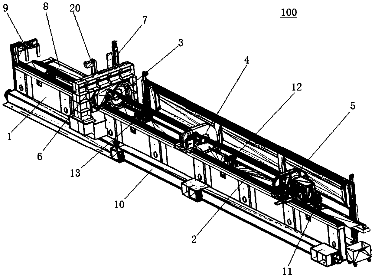
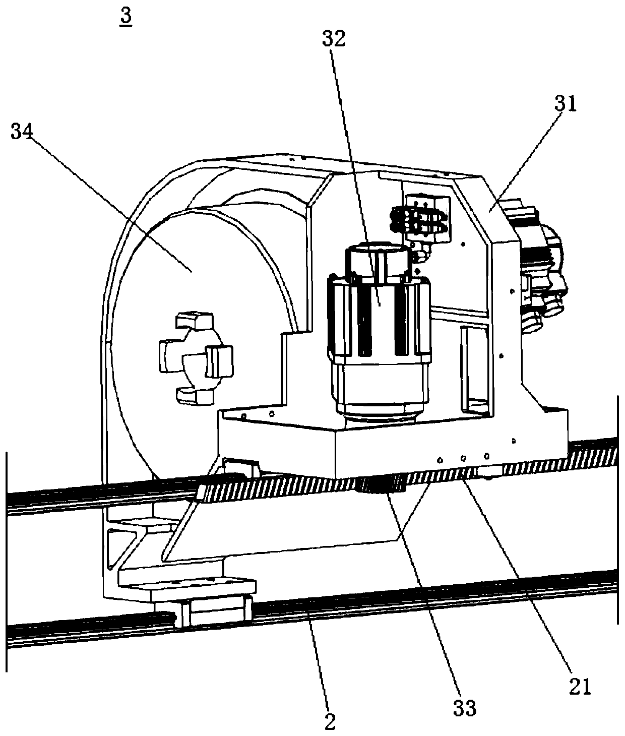
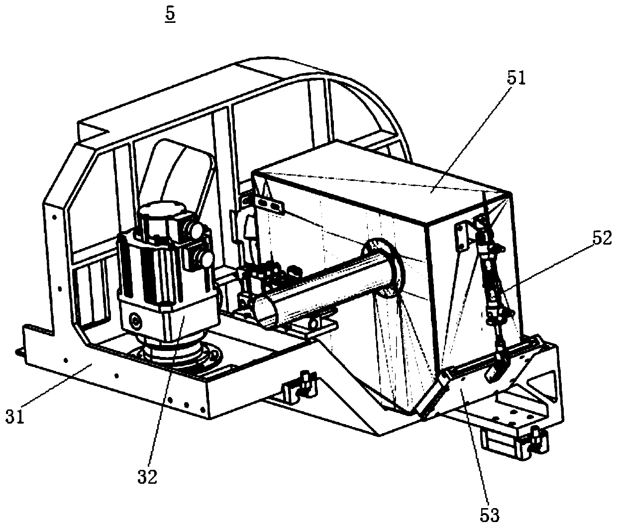
[0033] Please refer to Figure 1-Figure 11 , This embodiment is a three-chuck laser pipe cutting machine device 100, which includes a machine tool 1, a slide rail 2 arranged in parallel on the machine tool 1, a front chuck unit 3 slidable on the slide rail 2, and a middle chuck unit 4 With the rear chuck unit 5, the beam support 6 located on the machine tool 1, the laser cutting head 7 provided on the beam support 6, and the blanking pallet unit 8 located on the front side of the laser cutting head 7 and movable up and down relative to the machine tool 1. , A blanking clamping unit 9 located at the front end of the machine tool 1 to assist blanking, and a number of supporting and clamping units arranged at intervals along the slide rail 2 and movable up and down relative to the machine tool 1.

[0034] The machine tool 1 is provided with a rack 21 along the direction of the slide rail 2.

[0035] The front chuck unit 3, the middle chuck unit 4, and the rear chuck...


PUM


Abstract

The invention discloses a three-chuck laser pipe cutter device. The three-chuck laser pipe cutter device comprises a machine tool, sliding rails, a front chuck unit, a middle chuck unit, a back chuckunit, a transverse beam support, a laser cutting head, a material-falling supporting plate unit, a discharging clamping unit and a plurality of supporting clamping units, wherein the sliding rails arearranged on the machine tool in parallel; the front chuck unit, the middle chuck unit and the back chuck unit can slide on the sliding rails; the transverse beam support is located above the machinetool; the laser cutting head is arranged on the transverse beam support; the material-falling supporting plate unit is located on the front side of the laser cutting head and can move up and down relative to the machine tool; the discharging clamping unit is located at the front end of the machine tool and assists in material falling; and the plurality of supporting clamping units are arranged atintervals along the sliding rails and can move up and down relative to the machine tool. By means of the three-chuck laser pipe cutter device, the pipe loading capacity and cutting efficiency are greatly improved, the problem that the residual tail material is long is solved, and the raw material cost is reduced.

Description

【Technical field】 [0001] The invention belongs to the technical field of automatic feeding, in particular to a three-chuck laser pipe cutting machine device. 【Background technique】 [0002] The traditional pipe cutting machine is composed of two chucks, which can only process simple pipes. For the processing of super long pipes, the centrifugal swing in the middle of the pipes cannot be avoided during high-speed rotation cutting, which will affect the processing accuracy. The two-chuck pipe cutting machine cannot process products that require a relatively long blanking length. The front end of the pipe protrudes beyond a certain length and will sag under the action of gravity. It will cause swing when rotating, which will affect the processing accuracy. The bearing capacity of the two-chuck pipe cutting machine is insufficient for processing heavy pipes. The tailings remaining after cutting by the traditional two-chuck pipe cutting machine are relatively long, resulting in ...

Claims


Application Information

Patent Timeline
IPC IPC(8): B23K26/38B23K26/70B23K37/053
CPCB23K26/38B23K26/702B23K37/053B23K2101/06
Inventor 黄蛟
Owner SUZHOU QUICK LASER TECH
Why Eureka
Try Eureka