
A grinding machine with automatic closing function

A self-closing, functional technology, applied in the direction of manufacturing tools, grinding/polishing equipment, grinding/polishing safety devices, etc., can solve problems such as burns and scalds, splashes on people, and potential safety hazards, and achieve the goal of avoiding splashes in gaps Effect

Active Publication Date: 2021-01-05
CHONGQING XINGJI GEAR
View PDF23 Cites 0 Cited by
  • Summary
  • Abstract
  • Description
  • Claims
  • Application Information

AI Technical Summary

Problems solved by technology

[0003] During the grinding process of the grinding machine, the grinding parts need to be placed inside the grinding chamber for grinding. Therefore, the protective door of the grinding machine is extremely important. The existing protective door has the disadvantage of not being completely closed. If the protective door of the machine tool is completely closed, the sparks generated during the grinding process will splash out of the machine tool, and even splash on people, causing burns and scalding people. Once the sparks splash on the external circuit, it will cause damage to the circuit and even cause a fire , has a greater security risk

Method used


Image

  • A grinding machine with automatic closing function
  • A grinding machine with automatic closing function
  • A grinding machine with automatic closing function

Examples


Embodiment 1

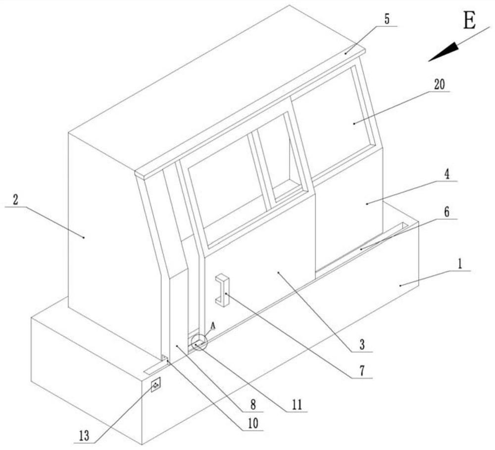
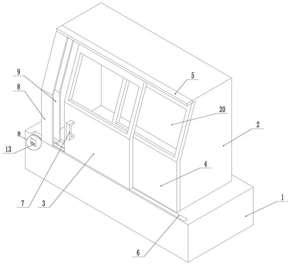
[0042] The embodiment is basically as attached figure 1 Shown: a grinding machine with automatic closing function, including a workbench 1, a grinding wheel arranged on the workbench 1, a driving unit for driving the grinding wheel to rotate, and a clamping unit for clamping workpieces. In this embodiment, the grinding wheel and the driving unit and The clamping units all adopt the basic equipment of the grinding machine in the prior art, and in this embodiment, the automatic closing function of the grinding machine is mainly realized, so the grinding wheel, the driving unit and the clamping unit are not shown in the figure.

[0043]Workbench 1 is provided with protective cover 2, and protective cover 2 all covers emery wheel and clamping unit inside it, and in the present embodiment, with the position that the operator stands and operates in the process of processing (such as the operator's work when installing the workpiece position) as the front side of the protective cover...

Embodiment 2

[0055] like Figure 5 As shown, a grinding machine with an automatic sealing function differs from Embodiment 1 in that: the inside of the workbench 1 is hollow, and an air supply unit is installed in the workbench 1 through bolts. The air supply unit in this embodiment is an existing There is an air compressor 18 in the art.

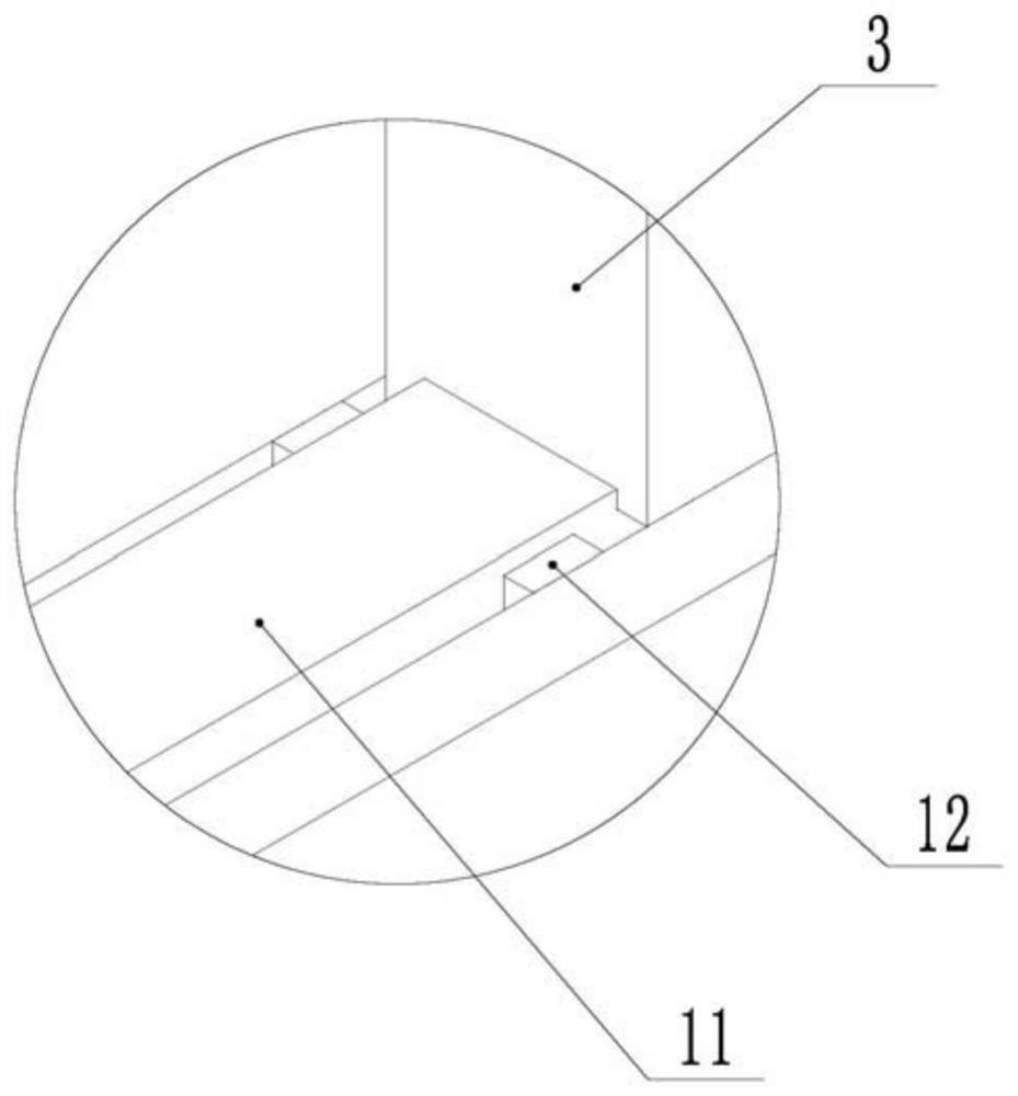
[0056] combine Image 6 and Figure 7 As shown, the side of the scraper 11 facing the fixed door 4 is welded and fixed with an extension plate 16, and the top of the extension plate 16 is welded and fixed to the bottom end of the sliding door 3. The insides of the scraper 11 and the extension plate 16 are all hollow, and the scraper block 11 and the extension plate 16 are welded and fixed to each other, and one end of the scraper block 11 and the extension plate 16 is connected to each other, so that the scraper block 11 and the extension plate 16 are connected to each other. The air outlet hole 17 of the air outlet pipe 19 is arranged between the ex...

Embodiment 3

[0059] like Figure 8 As shown, a grinding machine with automatic closing function differs from Embodiment 1 in that: the side of the limit block 8 away from the sliding door 3 is slidably connected with the pull plate 21 capable of blocking the sliding door 3 along the length direction of the chute 6 , combined with Figure 9 and Figure 10 As shown, the pull plate 21 is inserted into the limit groove 9 of the limit block 8, and the shape of the pull plate 21 in this embodiment is similar to the shape of the limit block 8, so that the pull plate 21 can be in the limit groove 9 Normal sliding.

[0060] combine Figure 8 As shown, the first guide groove 22 provided on the slide plate 5 runs through the top end of the slide plate 5 and the bottom end of the slide plate 5, and the top end of the sliding door 3 is welded and fixed with a first rack 24, and the first rack 24 is fixed along the first guide. The slot 22 slides in the longitudinal direction, and the top of the pro...


PUM


Abstract

The invention belongs to the technical field of grinding machine equipment, and particularly discloses a grinding machine with an automatic sealing function. The grinding machine comprises a workbench, wherein a protective cover is arranged on the workbench, one side of the protective cover is provided with a protective door, the protective door includes a fixed door and a sliding door, the fixeddoor is fixedly connected with the workbench, a sliding groove is formed in the workbench, the sliding door is in sliding fit with the sliding groove, a limiting block is connected to one side, away from the fixed door, of the protective cover, a limiting groove is formed in one side, facing the sliding door, of the limiting block, one side, away from the fixed door, of the sliding door can slideinto the limiting groove, a scraping block is fixedly connected to the bottom of the sliding door, scraping plates are arranged on the two sides of the scraping block correspondingly, a through grooveallowing the scraping block to pass is formed in the lower portion of the limiting block, a receiving groove is formed in the workbench, and the receiving groove communicates with one end, away fromthe fixed door, of the sliding groove. According to the grinding machine, after an operator pulls the protective door, the protective door can be completely closed, and spark sputtering is avoided.

Description

technical field [0001] The application of the present invention belongs to the technical field of grinding machine equipment, and specifically discloses a grinding machine with an automatic closing function. Background technique [0002] A grinding machine is a machine tool that uses abrasive tools to grind the surface of a workpiece. Most grinding machines use high-speed rotating grinding wheels for grinding. [0003] During the grinding process of the grinding machine, the grinding parts need to be placed inside the grinding chamber for grinding. Therefore, the protective door of the grinding machine is extremely important. The existing protective door has the disadvantage of not being completely closed. If the protective door of the machine tool is completely closed, the sparks generated during the grinding process will splash out of the machine tool, and even splash on people, causing burns and scalding people. Once the sparks splash on the external circuit, it will caus...

Claims


Application Information

Patent Timeline
Patent Type & Authority Patents(China)
IPC IPC(8): B24B55/04B24B55/06
CPCB24B55/04B24B55/06
Inventor 李传向朱加平
Owner CHONGQING XINGJI GEAR
Learn More