Self-excited oscillation cavitation impinging stream reactor

A technology of impinging flow reactor and cavitator, which is applied in chemical instruments and methods, mechanical oscillation water/sewage treatment, special compound water treatment, etc., can solve the problem of small cavitation area, large energy consumption of ultrasonic cavitation, and application The scope of the water is small and other problems, to achieve the effects of high cavitation intensity, enhanced sewage treatment efficiency, and high space utilization

Pending Publication Date: 2020-03-27
BEIJING UNIV OF TECH
View PDF18 Cites 9 Cited by
  • Summary
  • Abstract
  • Description
  • Claims
  • Application Information

AI Technical Summary

Problems solved by technology

At present, cavitation technologies that have been studied more include hydraulic cavitation and ultrasonic cavitation. Ultrasonic cavitation consumes a lot of energy and the cavitation area is relatively small, so its industrial application range is very small.

Method used


Image

  • Self-excited oscillation cavitation impinging stream reactor
  • Self-excited oscillation cavitation impinging stream reactor
  • Self-excited oscillation cavitation impinging stream reactor

Examples


Embodiment Construction

[0021] The present invention will be described in further detail below in conjunction with accompanying drawing:

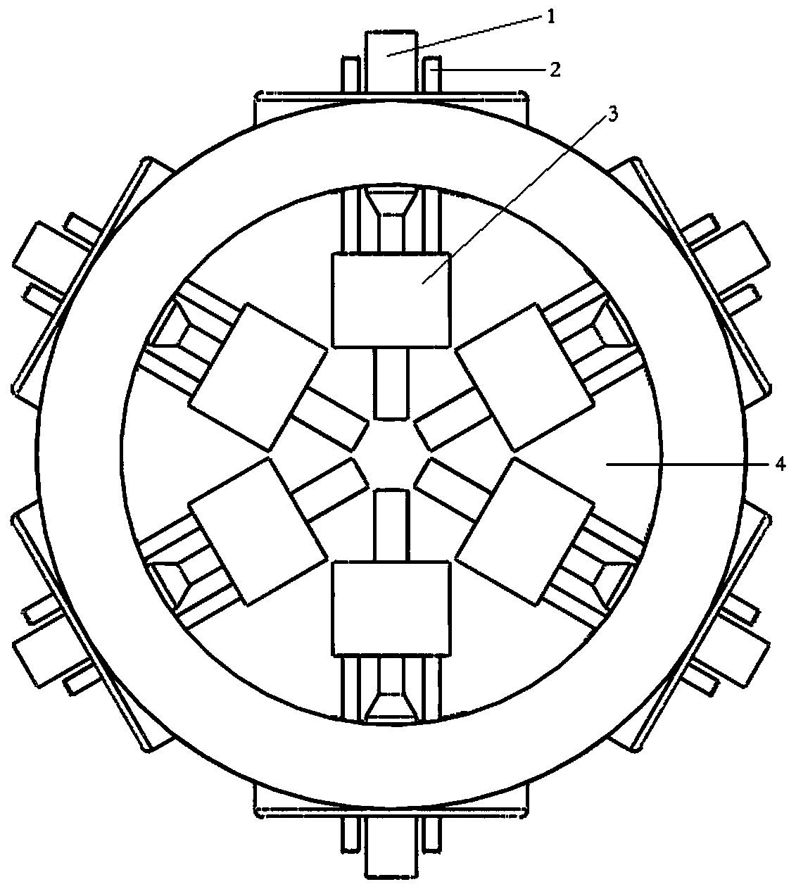
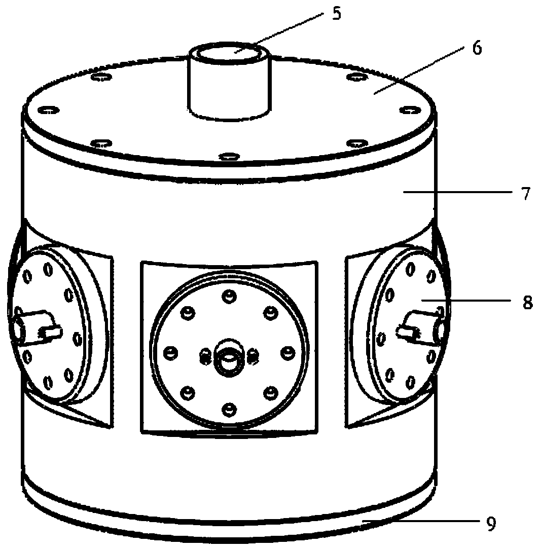
[0022] The invention provides a self-excited oscillation cavitation impingement flow reactor. figure 1 It is a schematic diagram of the internal structure of a self-excited oscillating cavitation impinging flow reactor of the present invention. figure 2 It is a front view of a self-excited oscillating cavitation impinging flow reactor of the present invention. Such as figure 1 figure 2 As shown, the present invention includes a liquid inlet pipe 1, an air inlet pipe 2, a cavitator 3, an impact chamber 4, a liquid outlet pipe 5, an upper cover plate 6, a wall plate 7, a flange plate 8, and a lower cover plate 9.

[0023] Such as figure 1 figure 2 As shown, the self-excited oscillating cavitation impingement flow reactor liquid inlet pipes can be six or other even numbers, evenly distributed on the periphery of the impact cavity, wherein the impact cavity ca...


PUM


Abstract

The invention discloses a self-excited oscillation cavitation impinging stream reactor which comprises a liquid inlet pipe, a gas inlet pipe, a cavitator, an impact cavity and a liquid outlet pipe. Apipe connector is mounted on an upper cover plate and used for being connected with the liquid outlet pipe and allowing a liquid to flow out; a water inlet pipe and a flange plate are connected through threads, and the distance between outlets of the self-excited oscillation cavitator can be changed by adjusting the screwing length of the threads. The water inlet pipe is in threaded connection with a self-excited oscillator. The self-excited oscillation cavitator is located in the impact cavity, liquid enters the self-excited oscillation cavitator through the liquid inlet pipe, cavitation is generated, cavitation jet flow is formed, multiple strands of liquid jet flows collide with one another at a high speed in the center of the impact cavity, and cavitation is effectively enhanced; meanwhile, plasma can be introduced into the cavitation process, and the generation efficiency of hydroxyl radicals is improved. The reaction process can be strengthened, the hydrodynamic cavitation strength is improved, and the degradation efficiency of organic wastewater is improved.

Description

technical field [0001] The invention relates to impinging flow hydraulic cavitation equipment, in particular to a self-excited oscillating cavitation impinging flow reactor which comprehensively utilizes self-excited oscillating cavitation jet and impinging flow technology to significantly improve cavitation and organic sewage treatment effects. Background technique [0002] With the rapid development of urbanization and society. This has greatly increased water consumption and sewage discharge, but the relative lag of sewage treatment facilities has caused a large amount of sewage to be discharged directly without treatment, resulting in a great threat to the surrounding environment and human life. The traditional technology for treating organic sewage has certain limitations and can no longer meet the new environmental protection needs. Therefore, it is necessary to develop more advanced sewage treatment technology. [0003] As a new type of advanced oxidation process (Ad...

Claims


Application Information

Patent Timeline
Patent Type & Authority Applications(China)
IPC IPC(8): C02F1/34C02F1/30C02F1/72C02F101/30
CPCC02F1/30C02F1/34C02F1/72C02F2101/30C02F2305/023
Inventor 聂松林李欧阳纪辉冯欣
Owner BEIJING UNIV OF TECH
Why Eureka
Try Eureka