Rapid cloth cleaning equipment for textile processing

A kind of cleaning equipment and fast technology, applied in the direction of textile processing machine accessories, textile material cleaning device, textile material treatment, etc., can solve the problems of high heat consumption, improper rubbing force, cloth damage, etc., and achieve good drying effect and clean Simple and convenient effect

Inactive Publication Date: 2020-03-27
安徽云至信电子商务有限公司
View PDF0 Cites 14 Cited by
  • Summary
  • Abstract
  • Description
  • Claims
  • Application Information

AI Technical Summary

Problems solved by technology

[0007] Existing cloth cleaning is usually done manually by rubbing and cleaning. This method is time-consuming and laborious. Improper rubbing strength can also cause problems such as cloth damage. There are also cleaning devices instead of manual labor, and the cleaning device usually sprays on the cloth. Rinse, this cleaning method is simple and fast, but the cleaning effect is relatively poor; and the general cleaning device directly enters the drying device after the cloth is cleaned, the water content in the cloth is large, and it is easy to accumulate water in the drying box, and It takes a long time to dry and consumes more heat

Method used


Image

  • Rapid cloth cleaning equipment for textile processing
  • Rapid cloth cleaning equipment for textile processing
  • Rapid cloth cleaning equipment for textile processing

Examples


Embodiment 1

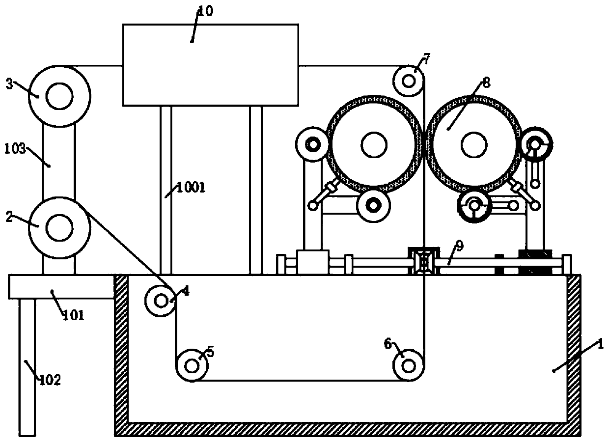
[0044] Please refer to the accompanying drawings, the present invention provides a technical solution: a rapid cleaning equipment for textile processing cloth, including a cleaning tank 1, a feeding cylinder 2, a material receiving cylinder 3, a drying mechanism 8, a drying mechanism 10 and an adjusting mechanism 9 , the left side of the cleaning tank 1 is fixed with a fixed plate 1305101, the bottom surface of the fixed plate 1305101 is fixed with a support leg 102, and the top surface is fixed with a fixed frame 103. The lower part and the upper part of the frame 103, and the material receiving cylinder 3 is connected with a material receiving motor, the upper left part of the cleaning tank 1 is rotatably connected with the first guide wheel 4, and the lower right side of the first guide wheel 4 is rotatably connected with a The second guide wheel 5 and the third guide wheel 6, the drying mechanism 8 is located above the third guide wheel 6, and the top of both side walls of ...

Embodiment 2

[0052] On the basis of Embodiment 1, a cleaning mechanism 11 is also included, and the cleaning mechanism 11 includes two connecting plates 1104 arranged symmetrically, and two parallel fixed cylinders 1101 are arranged between the bottoms of the two connecting plates 1104, A rotating shaft 1105 is fixed on the upper part of the connecting plate 1104 , and one end of the rotating shaft 1105 passes through the side wall of the cleaning tank 1 and is connected with the swing mechanism 13 .

[0053] The middle of the fixed cylinder 1101 is rotatably connected with a connecting shaft 1102, and the connecting shaft 1102 is fixedly connected with one of the connecting plates 1104. A plurality of rotating grooves are evenly arranged on the side of the fixing cylinder 1101 along the circumferential direction, and the rotating grooves A roller 1103 is arranged in the middle, and a part of the side of the roller 1103 is exposed in the rotating groove. Both ends of the fixed cylinder 1101...

Embodiment 3

[0057] On the basis of the second embodiment, it also includes two water spray pipes 12, the two water spray pipes 12 are symmetrically arranged above the third guide wheel 6, and the two water spray pipes 12 are connected with the same water pump, and the two water spray pipes 12 are connected with the same water pump. One side of the cleaning tank 1 is provided with a water tank, and the water pump is located in the water tank.

[0058] When the cloth moves vertically to the water surface of the cleaning tank 1 through the action of the third guide wheel 6 and the fourth guide wheel 7, the cloth is rinsed again through the water spray pipe 12 to avoid the floating dust on the surface of the water layer from adhering to Problems such as incomplete cleaning caused by the surface of the cloth.


PUM


Abstract

The invention discloses rapid cloth cleaning equipment for textile processing, and belongs to the technical field of textile processing. The rapid cloth cleaning equipment comprises a cleaning tank, adischarging cylinder, a material collecting cylinder, a drying mechanism, a hot air drying mechanism and adjusting mechanisms. According to the rapid cloth cleaning equipment for textile processing,the cloth is discharged through the discharging cylinder, and then the cloth is movably cleaned in water through the effects of a first guide wheel, a second guide wheel and a third guide wheel; thenwater absorption is carried out through sponge layers on two oppositely rotating drying cylinders after cleaning is performed, and hot air drying is conducted through the hot air drying mechanism after water absorption is performed; when the sponge layer after water absorption is subjected to the extrusion of a first water squeezing cylinder, the sponge layer is kept at relative humidity so as tocontinuously absorb water and dry the subsequent cloth; a second water squeezing cylinder further squeezes the sponge layer, and after the sponge layer works for a period of time, the sponge layer issprayed with clean water through a water outlet pipe; and then a second water collecting pipe is adopted for squeezing and de-watering, and the sponge layer is cleaned, so that the sponge layer is kept relatively clean.

Description

technical field [0001] The invention relates to the technical field of textile processing, in particular to a rapid cleaning device for cloth used in textile processing. Background technique [0002] Textile fabrics, that is, textile fabrics, are divided into weft-knitted fabrics and warp-knitted fabrics according to the weaving method. Weft-knitted fabrics are often made of low-elastic polyester yarn or special-shaped polyester yarn, nylon yarn, cotton yarn, wool yarn, etc. Circle weaves, etc., are woven on various weft knitting machines. China is one of the first countries in the world to produce textile fabrics. [0003] Chinese machine tool textiles originated from the spinning wheel and waist machine of the Neolithic Age 5,000 years ago. Simple reeling wheels, spinning wheels, and looms with traditional performance appeared one after another in the Western Zhou Dynasty. Jacquard looms and diagonal looms were widely used in the Han Dynasty. After the Tang Dynasty, Chi...

Claims


Application Information

Patent Timeline
Patent Type & Authority Applications(China)
IPC IPC(8): D06B3/20D06B15/04D06B23/02D06B23/04D06B23/30
CPCD06B3/20D06B15/046D06B23/02D06B23/023D06B23/04D06B23/30
Inventor 万燕
Owner 安徽云至信电子商务有限公司
Why Eureka
Try Eureka