
Shock absorption skid-mounted comprehensive pipe gallery structure and construction method

A comprehensive pipe gallery and skid-mounted technology, which is used in infrastructure engineering, underwater structures, artificial islands, etc., can solve the problem that the pipe gallery structure cannot be cast and formed at one time, the lack of shock absorption measures and shock absorption structures, and the civil construction period. long and other problems, to achieve the effect of simple structure, reduced on-site workload, and shortened construction period

Pending Publication Date: 2020-03-27
CHINA RAILWAY ERYUAN ENG GRP CO LTD
View PDF0 Cites 0 Cited by
  • Summary
  • Abstract
  • Description
  • Claims
  • Application Information

AI Technical Summary

Problems solved by technology

At present, the structure of underground comprehensive pipe gallery mostly adopts cast-in-place reinforced concrete structure. There are many construction procedures such as formwork support, steel bar binding, concrete curing, and formwork removal. The construction process is complicated, and the pipe gallery structure cannot be poured into shape at one time. , it is necessary to reserve sufficient time intervals for pouring concrete in sections, and the civil construction period is relatively long
At the same time, the traditional anti-seismic design of the pipe gallery structure usually adopts the method of anti-seismic support. For the pipe gallery structure itself, there is a lack of direct and effective shock-absorbing measures and shock-absorbing structures.

Method used


Image

  • Shock absorption skid-mounted comprehensive pipe gallery structure and construction method
  • Shock absorption skid-mounted comprehensive pipe gallery structure and construction method
  • Shock absorption skid-mounted comprehensive pipe gallery structure and construction method

Examples


Embodiment Construction

[0018] The present invention will be further described below in conjunction with the accompanying drawings and embodiments.

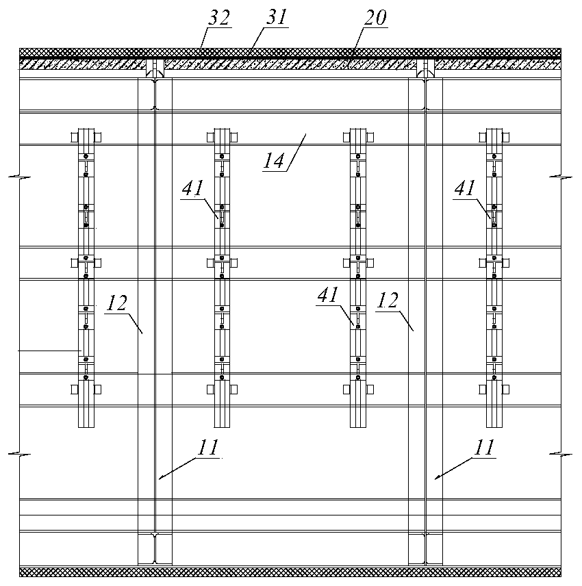
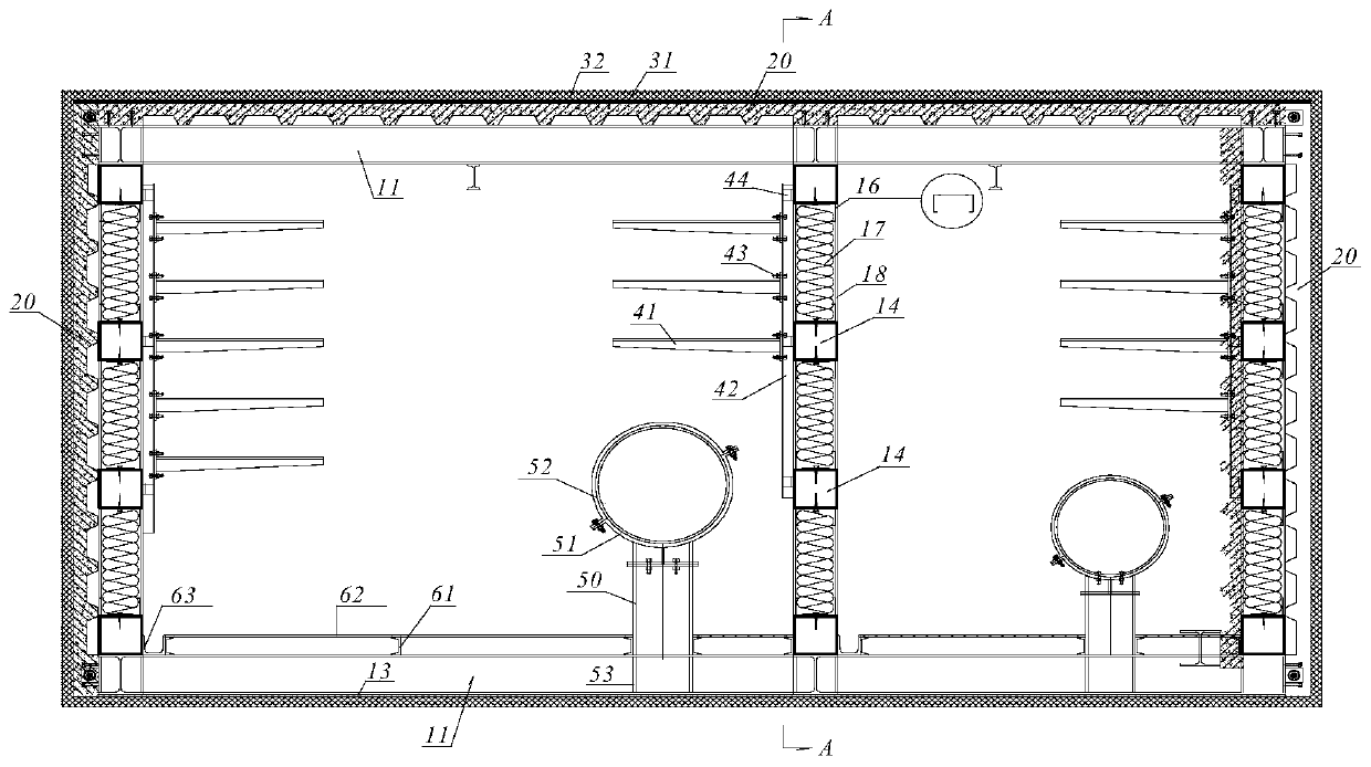
[0019] refer to figure 1 and figure 2 , a shock-absorbing skid-mounted comprehensive pipe gallery structure of the present invention includes a main structure of the pipe gallery and a shock-absorbing structure. The steel frame structure is welded by steel beams 11 and steel columns 12, the bottom of the steel frame structure is welded with a back-sealing steel plate 13, and the profiled steel plate concrete composite plate 20 is fixedly arranged on the top and two lateral sides of the steel frame structure. The combination of shaped steel plate and reinforced concrete bears the earth pressure together. Firewalls are set in the middle and two lateral sides of the steel frame structure, side wall support systems are set on the fire wall, and pipeline support structures and pedestrian passage structures are set at the bottom of the steel frame structur...


PUM


Abstract

The invention discloses a shock absorption skid-mounted comprehensive pipe gallery structure and a construction method, so that the overall factory prefabrication and on-site hoisting splicing are achieved, the on-site workload is effectively reduced, and the construction period is greatly shortened. The pipe gallery structure comprises a pipe gallery main body structure and a shock absorption structure; the pipe gallery main body structure is composed of a steel frame structure, firewalls and profiled steel sheet concrete composite plates; the steel frame structure is formed by welding steelbeams and steel columns, a bottom sealing steel plate is welded to the bottom of the steel frame structure, and the profiled steel sheet concrete composite plates are fixedly arranged on the top and the two transverse side faces of the steel frame structure; firewalls are arranged in the middle and on the two transverse side faces in the steel frame structure, side wall support systems are arranged on the firewalls, and a pipeline supporting structure and a pedestrian path structure are arranged at the bottom of the steel frame structure; the shock absorption structure comprises a longitudinalshock absorption layer and a transverse shock absorption layer; the elastic transverse shock absorption layer is arranged around the pipe gallery main body structure, and the longitudinal shock absorption layer is arranged between the transverse shock absorption layer and the top surface of the pipe gallery main body structure.

Description

technical field [0001] The invention relates to a comprehensive pipe gallery, in particular to a shock-absorbing skid-mounted comprehensive pipe gallery structure and a construction method. Background technique [0002] With the continuous improvement of the policy environment for the construction of domestic urban comprehensive pipe corridors and the continuous increase in capital investment, the overall development trend of domestic comprehensive pipe corridors is good. At present, the underground comprehensive pipe gallery structure mostly adopts cast-in-place reinforced concrete structure, and there are many construction procedures such as formwork support, steel bar binding, concrete curing, and formwork removal. The construction process is complicated, and the pipe gallery structure cannot be poured into shape at one time. , Concrete pouring in sections needs to reserve sufficient time intervals, and the civil construction period is longer. At the same time, the tradi...

Claims


Application Information

Patent Timeline
IPC IPC(8): E02D29/045E02D31/08
CPCE02D29/10E02D31/08
Inventor 谷勇席林罗庆毛嘉川胡进刘浩宇李霖霖
Owner CHINA RAILWAY ERYUAN ENG GRP CO LTD
Learn More