Angle-equipped cooling and positioning structure for flame tube head of aero-engine combustion chamber

A flame tube head and aero-engine technology, applied in the field of aero-engines, can solve the problems affecting the use of the flame tube, unfavorable cooling, unfavorable maintenance, etc., and achieve the effects of simple and feasible structure, increased life, and good cooling effect

Inactive Publication Date: 2020-03-27
AECC SICHUAN GAS TURBINE RES INST
View PDF3 Cites 12 Cited by
  • Summary
  • Abstract
  • Description
  • Claims
  • Application Information

AI Technical Summary

Problems solved by technology

However, the welding structure of the large-sized head increases the complexity of the head, which is not conducive to cooling; at the same time, the splash plate is easily damaged when exposed to high-temperature gas. Any damage to the splash plate in the welded structure will affect the entire flame tube use, not conducive to maintenance

Method used


Image

  • Angle-equipped cooling and positioning structure for flame tube head of aero-engine combustion chamber
  • Angle-equipped cooling and positioning structure for flame tube head of aero-engine combustion chamber
  • Angle-equipped cooling and positioning structure for flame tube head of aero-engine combustion chamber

Examples


Embodiment Construction

[0021] In order to make the object, technical solution and advantages of the present invention clearer, the present invention will be described in further detail below in conjunction with specific embodiments and with reference to the accompanying drawings.

[0022] The patent of the present invention will be introduced in detail below in conjunction with the accompanying drawings and specific implementation examples.

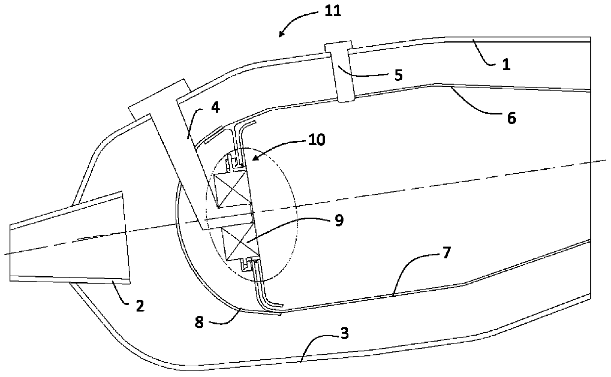
[0023] refer to figure 1 , is a schematic diagram of the cooling and positioning structure of the flame tube head of the aeroengine combustor, describing the outer casing 1, the diffuser 2, the inner casing 3, the nozzle 4, the electric nozzle 5, the flame tube outer ring 6, and the flame tube inner ring 7 , the relative positions of the cap 8, the swirler assembly 9 and the cooling positioning structure 10 of the flame cylinder head.

[0024] The cooling positioning structure 10 of the flame tube head is located behind the cap 8, and the swirler assembly 9 is...


PUM


Abstract

The invention discloses an angle-equipped cooling and positioning structure for a flame tube head of an aero-engine combustion chamber. The structure is suitable for various annular combustion chambers, and mainly comprises a cyclone mounting base (12), a head switching section (13), a splash disc (15), a self-locking nut (14) and the like. According to the structure, the flame tube head is simpleand feasible in structure, the temperature of each element of the head can be effectively reduced, and the cooling effect is good; compared with a conventional combustion chamber flame tube with a welded head, the flame tube only needs to be independently processed with the cyclone mounting base and the splash disc and then assembled, so that the production efficiency can be greatly improved; thesplash disc can expand towards the periphery when being heated, and heat stress is released, so that the service life of the splash disc is prolonged, and the service life of the flame tube is prolonged; and meanwhile, if the splash disc is damaged, parts can be replaced in time, so that maintenance is facilitated, and the structure has relatively good economic efficiency and very high practicalapplication value.

Description

technical field [0001] The invention belongs to the field of aero-engines, and mainly relates to a cooling and positioning structure for the head of a combustion chamber of an aero-engine. Background technique [0002] The design of the combustion chamber requires a certain amount of air intake in the head assembly. For the development trend of the modern combustion chamber, in terms of flow distribution, the percentage of the flow entering the head area is increased, and most of the airflow will enter the flame tube from the head. In order to improve the pollution emission characteristics and the ignition and extinguishing characteristics of the combustion chamber, the height of the head of the flame tube is larger than that of the conventional combustion chamber design, the size of the head device is also larger, and the structure is more complicated, so choose the appropriate head of the flame tube The cooling structure is very important to ensure the performance of the c...

Claims


Application Information

Patent Timeline
Patent Type & Authority Applications(China)
IPC IPC(8): F23R3/42F23R3/58F23R3/60
CPCF23R3/42F23R3/58F23R3/60F23R2900/03043
Inventor 卢加平房人麟时远李九龙张伟桂韬邓远灏黄顺洲
Owner AECC SICHUAN GAS TURBINE RES INST
Why Eureka
Try Eureka