
Fan-shaped test piece structure of high-pressure cabin type main combustion chamber

A technology of the main combustion chamber and hyperbaric chamber, which is applied in the field of aero-engines, can solve the problems that affect the test safety and the life of the test piece, reduce the test accuracy, and the weak capacity of the fan-shaped welding structure, so as to eliminate the leakage of the two channels and ensure the flow distribution. , Improve the effect of test safety

Active Publication Date: 2020-03-27
AECC SICHUAN GAS TURBINE RES INST
View PDF7 Cites 0 Cited by
  • Summary
  • Abstract
  • Description
  • Claims
  • Application Information

AI Technical Summary

Problems solved by technology

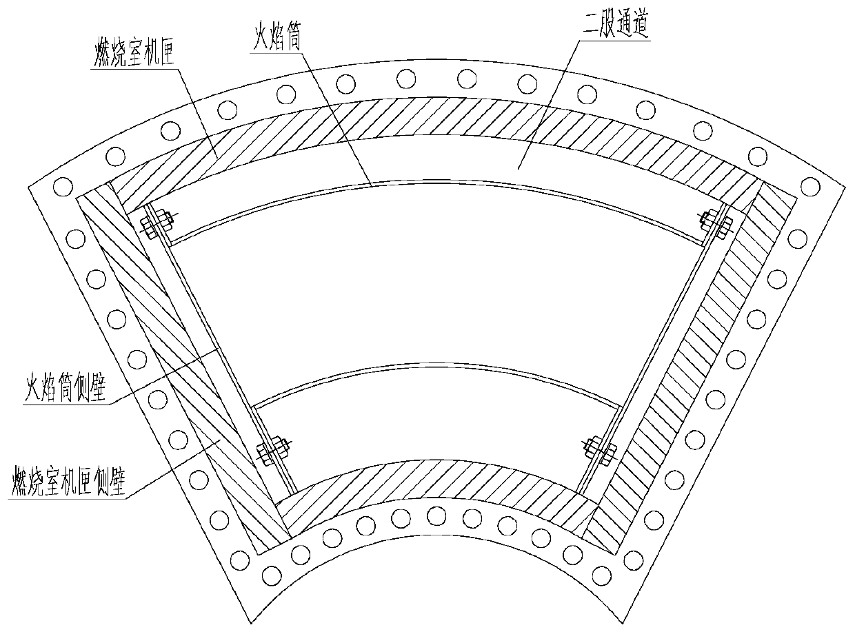
[0004] a) Combustion chamber casing with increased wall thickness compared with the real part is used as the load-bearing part. Its fan-shaped welded structure has weak ability to withstand high temperature and high pressure and transmit equipment load, and it is difficult to meet the strength design requirements, thus affecting the test safety and the test piece life;
[0005] b) The casing of the combustion chamber and the flame tube are assembled structures. In order to facilitate assembly and prevent thermal deformation from being uncoordinated, there is a gap between the side wall and edge of the flame tube and the casing of the combustion chamber, causing some airflow in the two channels to enter the side cavity (combustion chamber) during the test. chamber casing and the cavity on the side wall of the flame tube), thus affecting the flow distribution of the test piece and reducing the test accuracy;
[0006] c) Due to the differences in engine characteristics, aerodynamic parameters, and structural dimensions of different projects, each project designs a sector-shaped test piece according to its own needs, which is not universal and greatly increases the development cost and cycle

Method used


Image

  • Fan-shaped test piece structure of high-pressure cabin type main combustion chamber
  • Fan-shaped test piece structure of high-pressure cabin type main combustion chamber
  • Fan-shaped test piece structure of high-pressure cabin type main combustion chamber

Examples


Embodiment Construction

[0030] In order to make the object, technical solution and advantages of the present invention clearer, the present invention will be described in further detail below in conjunction with specific embodiments and with reference to the accompanying drawings.

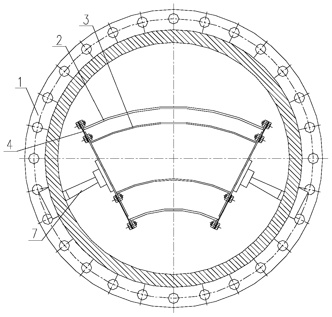
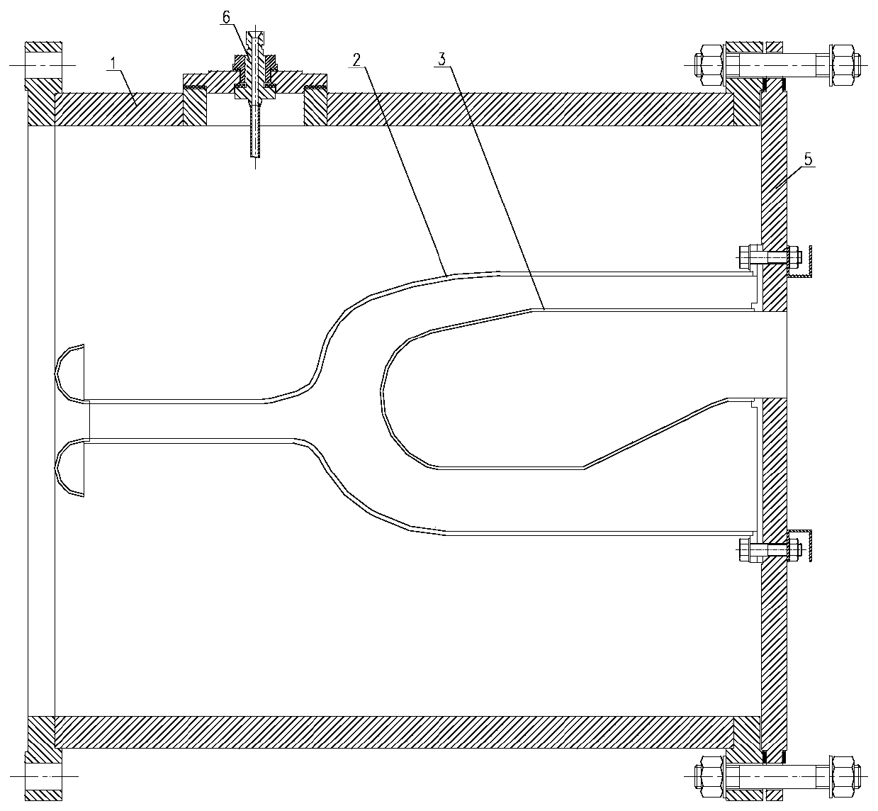
[0031] The present invention is a fan-shaped test piece structure of a hyperbaric chamber type main combustion chamber, which mainly consists of a load-bearing casing 1, a fan-shaped casing 2, a fan-shaped flame cylinder 3, a sealing side wall 4, a supporting flange 5, a fuel nozzle 6, and auxiliary supports. 7 components, simple and reliable structure, has a certain degree of versatility, and is suitable for high temperature and high pressure component test pieces.

[0032] The sealing side wall 4 is pressed and sealed by bolts to seal the side walls of the fan-shaped casing 2 and the fan-shaped flame tube 3 to form a closed secondary channel of the main combustion chamber, and has the ability to compensate for processing...


PUM


Abstract

The invention provides a fan-shaped test piece structure of a high-pressure cabin type main combustion chamber. A force bearing casing is cylindrical, a test section is arranged in the force bearing casing, and the test section comprises a fan-shaped flame tube and a fan-shaped casing; under the structure of the invention, the mechanical load and the test pressure in the test process are independently borne by the force bearing casing; a test section main body consisting of the fan-shaped casing and the fan-shaped flame tube only has the function of forming a flow channel and is not affected by the external load, the service life can be effectively prolonged, and the test safety of the test piece can be effectively improved;; the bearing casing and the supporting flange have certain universality and can contain a plurality of project fan-shaped test pieces, the test pieces are simple and reliable in structural form, good in manufacturability and convenient to assemble and disassemble,the machining cost can be remarkably saved, and the development period can be shortened.

Description

technical field [0001] The invention relates to the field of aero-engines, and is a sectoral test piece structure of a high-pressure chamber type main combustion chamber, and is also applicable to other high-temperature and high-pressure sectoral test piece designs. Background technique [0002] With the continuous development of advanced aviation technology, higher requirements are put forward for the high temperature ratio, high pressure ratio, high thrust-to-weight ratio and low fuel consumption of aero-engines. As one of the three core components of the engine, the main combustion chamber must have a higher combustion efficiency. Efficiency, lighter weight and longer life. In the process of engine development, the existing calculation and simulation methods have certain limitations, and cannot accurately simulate the working state and performance of the engine, which needs to be verified through a large number of tests. At present, due to the limitation of the test equi...

Claims


Application Information

Patent Timeline
IPC IPC(8): G01M15/04G01M15/02G01M15/14
CPCG01M15/02G01M15/04G01M15/14
Inventor 李向泓陈振辉吴悠李银怀徐华胜黎武
Owner AECC SICHUAN GAS TURBINE RES INST
Learn More