Motor device and electric toothbrush

A motor shaft and casing technology, applied in electromechanical devices, electric components, dentistry, etc., can solve the problems of reducing the assembly efficiency of motor devices, inability to accommodate electromagnetic components, and inconvenient coil winding, so as to improve high-end experience and improve motor performance. , the effect of reducing the overall weight

Pending Publication Date: 2020-03-27
东莞市米贝科技有限公司
View PDF0 Cites 0 Cited by
  • Summary
  • Abstract
  • Description
  • Claims
  • Application Information

AI Technical Summary

Problems solved by technology

[0003] At present, the connection structure between the stator iron core and the wire frame of the small vibration motor is an integral type (as shown in the attached figure 1 ), the stator core is located in the wire frame, when the coil is wound, the coil winding is very inconvenient due to the obstruction of the wire frame, which reduces the assembly efficiency of the motor device, and this structure leads to limited space in the wire frame, which cannot accommodate Electromagnetic components with higher output power further limit the performance of the motor

Method used


Image

  • Motor device and electric toothbrush
  • Motor device and electric toothbrush
  • Motor device and electric toothbrush

Examples


Embodiment Construction

[0025] Attached below figure 2 To attach Figure 8 , and specific embodiments will further illustrate the present invention.

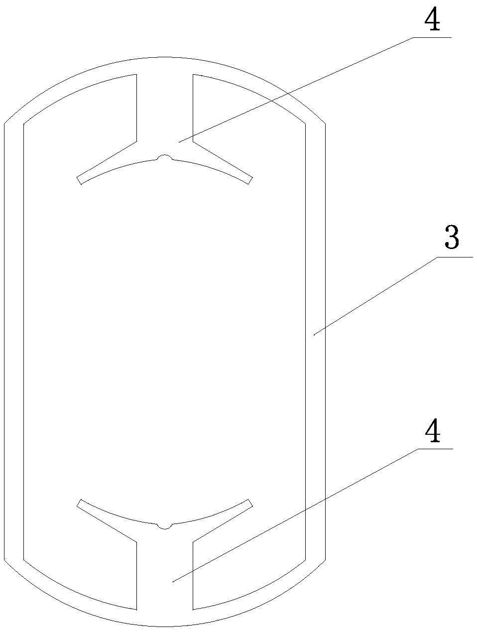
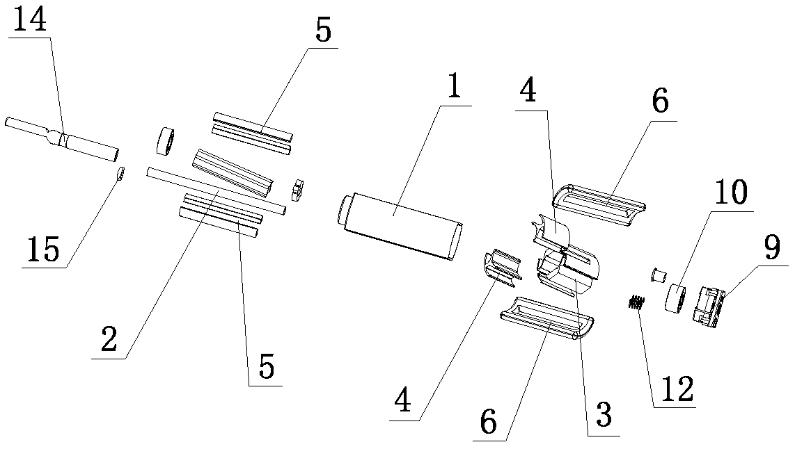
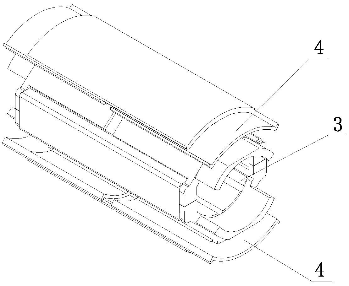
[0026] Such as Figure 2 to Figure 4 As shown, a motor device includes a casing 1, and the casing 1 is provided with a motor shaft 2, an insulating wire frame 3 and at least a pair of stator cores 4, and the stator core 4 is provided with a magnetic steel structure 5. The insulated wire frame 3 includes a first skeleton 31 and a second skeleton 32 arranged below the first skeleton 31, the first skeleton 31 and the second skeleton 32 have the same structure, and the first skeleton 31 and the second A first connecting frame body 33 is arranged between the skeletons 32, and is connected through the first connecting frame body 33; the first skeleton 31 is provided with a slot 34, and the stator core 4 includes a first arc punching piece 41 And the second arc-shaped punch 42 arranged below the first arc-shaped punch 41, a second connecting frame body 43...


PUM


Abstract

The invention relates to the technical field of motors, in particular to a motor device and an electric toothbrush. The motor device comprises a shell; a motor shaft, an insulation wire frame and at least one pair of stator iron cores are arranged in the shell, a magnetic steel structure is arranged in each stator iron core, the insulation wire frame comprises a first framework and a second framework, and a first connecting frame body is arranged between the first framework and the second framework and is connected through the first connecting frame body; the first framework is provided with an open groove, the stator iron core comprises a first arc-shaped punching sheet and a second arc-shaped punching sheet, and a second connecting frame body is arranged between the first arc-shaped punching sheet and the second arc-shaped punching sheet and connected with the first arc-shaped punching sheet and the second arc-shaped punching sheet through the second connecting frame body. Accordingto the invention, the stator iron core slides into the insulating wire frame; the coil winding, the stator core and the insulation coil holder are assembled in a split independent structure, so that the space structure in the insulation coil holder is expanded, the winding mode of the coil is simplified, the electromagnetic assembly with higher output power can be accommodated in the insulation coil holder, the motor can transmit higher torque, and the motor performance is improved.

Description

technical field [0001] The invention relates to the technical field of motors, in particular to a motor device and an electric toothbrush. Background technique [0002] With the improvement of living standards, consumers pay more and more attention to personal care. In the technical field of personal care products, such as electric toothbrushes, facial cleansers, massagers, etc., small vibration motors are generally used as driving devices. [0003] At present, the connection structure between the stator iron core and the wire frame of the small vibration motor is an integral type (as shown in the attached figure 1 ), the stator core is located in the wire frame, when the coil is wound, the coil winding is very inconvenient due to the obstruction of the wire frame, which reduces the assembly efficiency of the motor device, and this structure leads to limited space in the wire frame, which cannot accommodate Electromagnetic components with greater output power further limit ...

Claims


Application Information

Patent Timeline
IPC IPC(8): H02K1/17H02K1/18H02K3/34H02K3/50H02K5/16H02K5/24A61C17/26A61C17/34
CPCA61C17/26A61C17/34H02K1/17H02K1/18H02K3/345H02K3/50H02K5/161H02K5/24
Inventor 瞿德龙袁永智黄建辉
Owner 东莞市米贝科技有限公司
Why Eureka
Try Eureka