Water cooling device of electrical control system

A technology of electrical control system and water-cooling device, which is applied in the direction of electrical components, structural parts of electrical equipment, cooling/ventilation/heating transformation, etc., which can solve the problems of small mass transfer area of ​​electrical components and easy scale formation of heat dissipation pipes, etc., and achieve improvement Heat conduction efficiency, improved heat dissipation effect, and easy disassembly and installation

Inactive Publication Date: 2020-03-27
PAGMAN TECH (TAICANG) CO LTD
View PDF0 Cites 2 Cited by
  • Summary
  • Abstract
  • Description
  • Claims
  • Application Information

AI Technical Summary

Problems solved by technology

[0003] The existing water-cooling device generally installs the radiating pipe with the cooling liquid directly in the electrical control system, but the water-cooling method with this simple structure has a small mass transfer area with the electrical components required to dissipate heat, and the electrical components Most of the heat generated is conducted to the heat pipe through the air, and the heat dissipation effect needs to be improved to a certain extent. At the same time, the heat pipe used in the prior art is prone to scale after being used for a long time

Method used


Image

  • Water cooling device of electrical control system
  • Water cooling device of electrical control system
  • Water cooling device of electrical control system

Examples


Embodiment Construction

[0026] The present invention will be further described in detail below in conjunction with the accompanying drawings and specific embodiments.

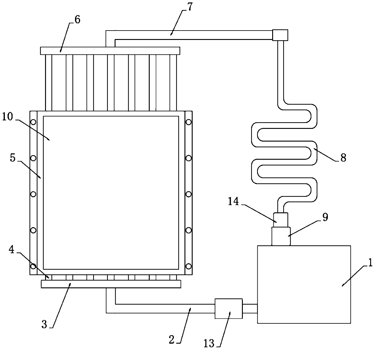
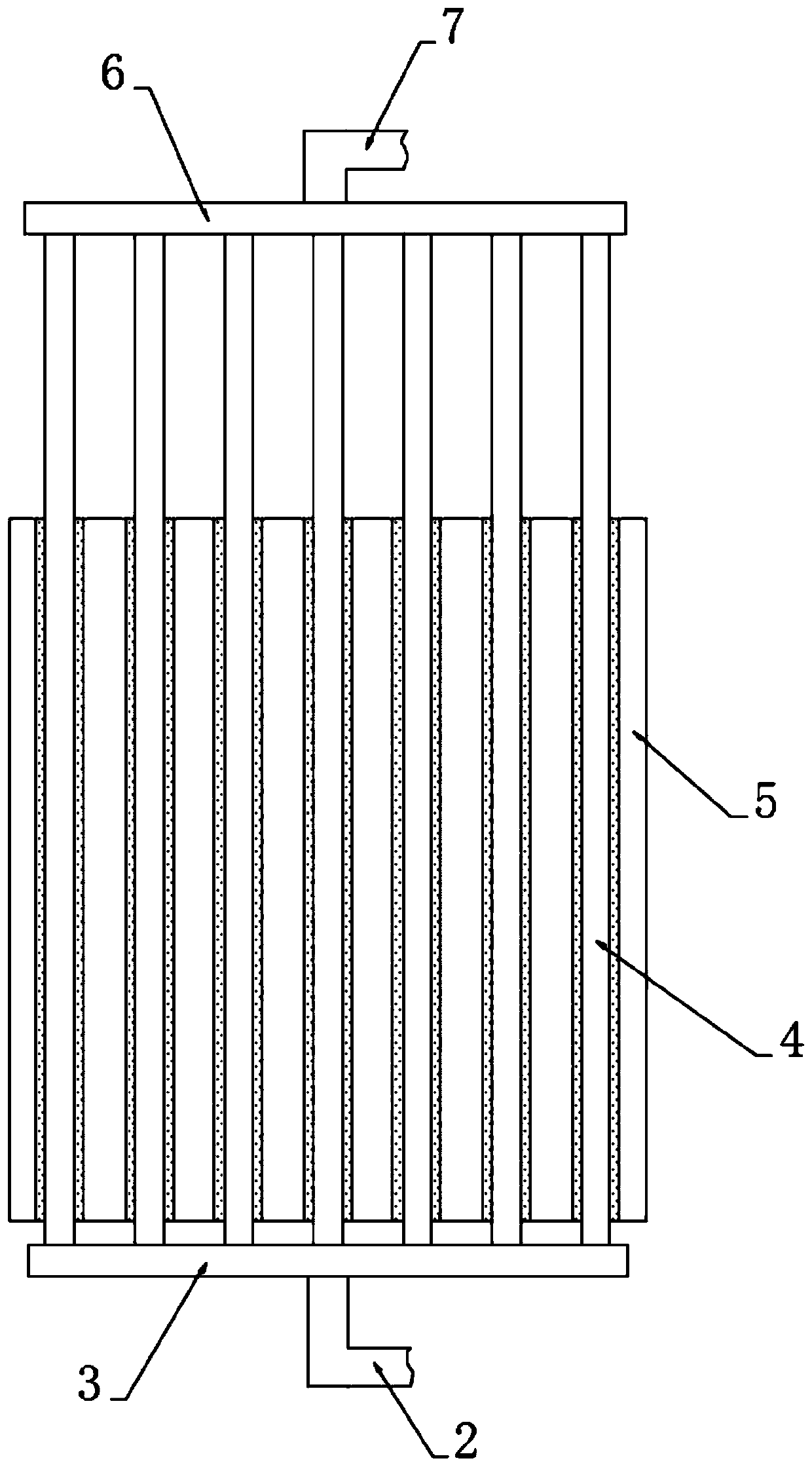
[0027] as attached figure 1 The water cooling device for an electrical control system of the present invention as shown includes a coolant water tank 1, the water outlet end of the coolant water tank 1 is fixedly connected with a lower horizontal pipe 3 through a water inlet pipe 2, and the coolant water tank 1 and the water inlet pipe 2 A magnetizer 13 is fixedly installed between them, and the upper ends of the lower horizontal tubes 3 are fixedly connected with water-cooled vertical tubes 4 at equal intervals along the horizontal direction, and the top ends of multiple water-cooled vertical tubes 4 are fixedly connected with upper horizontal plates matching the lower horizontal tubes 3 6. The top of the upper horizontal plate 6 is fixedly connected to the heat dissipation pipe 8 through the water outlet pipe 7, and the top of the h...


PUM


Abstract

The invention relates to a water cooling device of an electrical control system, belongs to the radiation field of electrical system. The water cooling device of an electrical control system comprisesa cooling liquid tank, the water outlet end of the cooling liquid water tank is fixedly connected with a lower transverse pipe through a water inlet pipe; a magnetizer is fixedly arranged between thecooling liquid water tank and the water inlet pipe; water-cooling vertical pipes are fixedly connected to the upper end of the lower transverse pipe at equal intervals in the horizontal direction ofthe lower transverse pipe; the heat conduction plate is directly installed on the heat conduction half shells embedded in the outer sides of the multiple water cooling vertical pipes. The heat conduction plate is in direct contact with the heating element, is easy to enlarge heat conduction area, the water-cooling vertical pipe arranged in the heat-conducting half shell takes away the heat of theheating element; meanwhile, heat in the air is taken away through the water cooling vertical pipes exposed out of the heat conduction half shells, the heat dissipation effect is effectively improved,the magnetizer is installed at the water outlet end of the cooling liquid water tank, magnetization treatment of cooling liquid is achieved, and scaling of the cooling liquid in all pipelines is effectively avoided.

Description

technical field [0001] The invention relates to the field of heat dissipation of electrical systems, in particular to a water cooling device for an electrical control system. Background technique [0002] The electrical control system is generally called the secondary control loop of electrical equipment. Different equipment has different control loops, and the control methods of high-voltage electrical equipment and low-voltage electrical equipment are also different. Specifically, the electrical control system refers to the combination of several electrical components to realize the control of one or some objects, so as to ensure the safe and reliable operation of the controlled equipment. The electrical control system will generate a lot of heat during high-intensity work. In the existing technology, water cooling or air cooling is mostly used to dissipate heat inside the electrical control system. The water cooling system is reliable because of its high cooling efficienc...

Claims


Application Information

Patent Timeline
Patent Type & Authority Applications(China)
IPC IPC(8): H05K7/20
CPCH05K7/20272H05K7/2039H05K7/20418H05K7/20445H05K7/20509
Inventor 王刚唐弇冬周皓
Owner PAGMAN TECH (TAICANG) CO LTD
Why Eureka
Try Eureka