Laser head of laser cutting machine

A laser cutting machine and laser head technology, which is applied in the field of laser heads, can solve the problems of easy generation of burrs in the cutting seam, not being able to face the cutting seam, and affecting the quality of cutting.

Active Publication Date: 2020-03-31
JINAN BODOR LASER CO LTD
View PDF16 Cites 6 Cited by
  • Summary
  • Abstract
  • Description
  • Claims
  • Application Information

AI Technical Summary

Problems solved by technology

However, in the actual production process, it is necessary to adjust the nozzle to be coaxial with the laser beam, otherwise the high-sp

Method used


Image

  • Laser head of laser cutting machine
  • Laser head of laser cutting machine
  • Laser head of laser cutting machine

Examples


Embodiment Construction

[0027] The present invention will be further described below in conjunction with the accompanying drawings and embodiments.

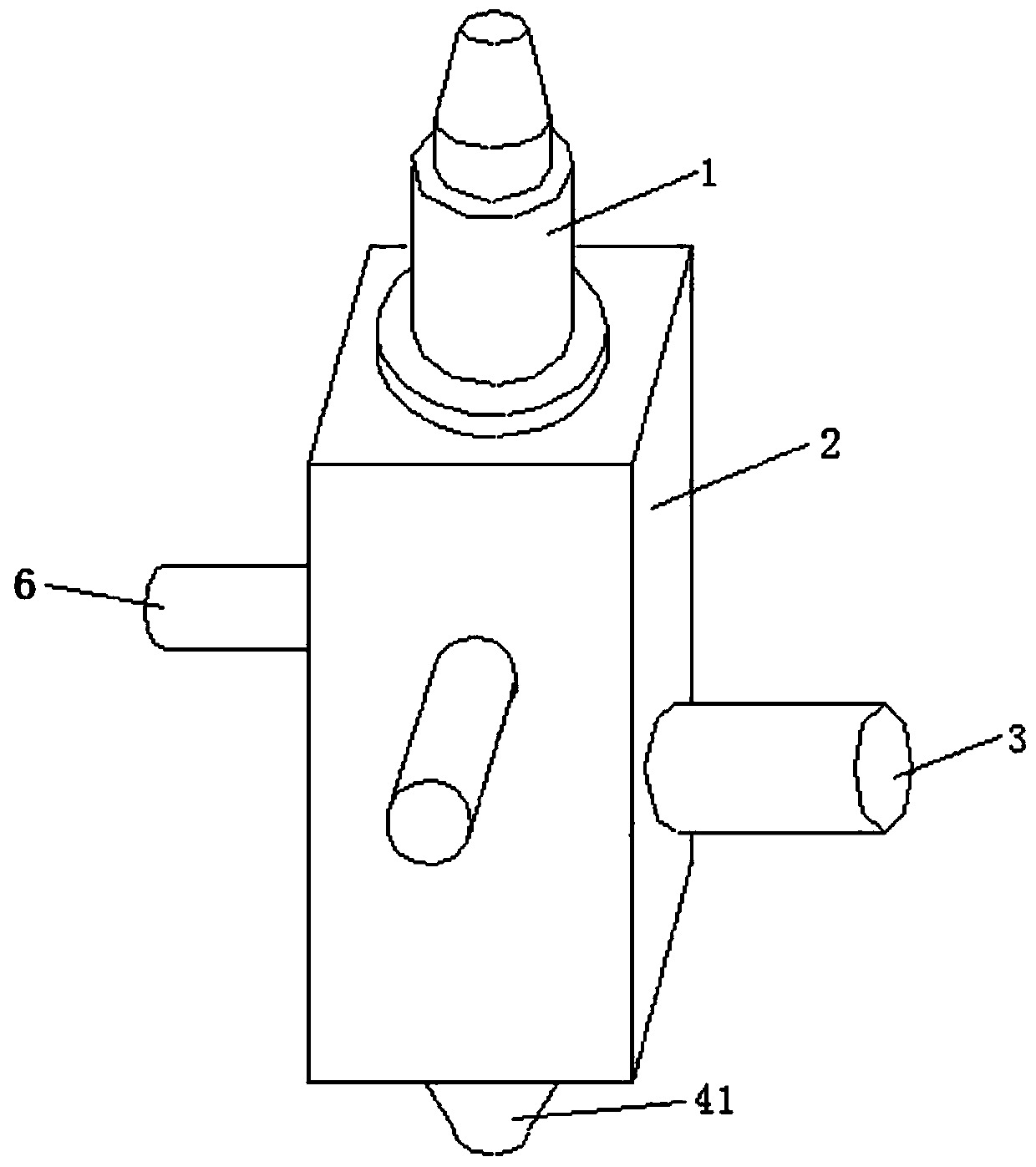
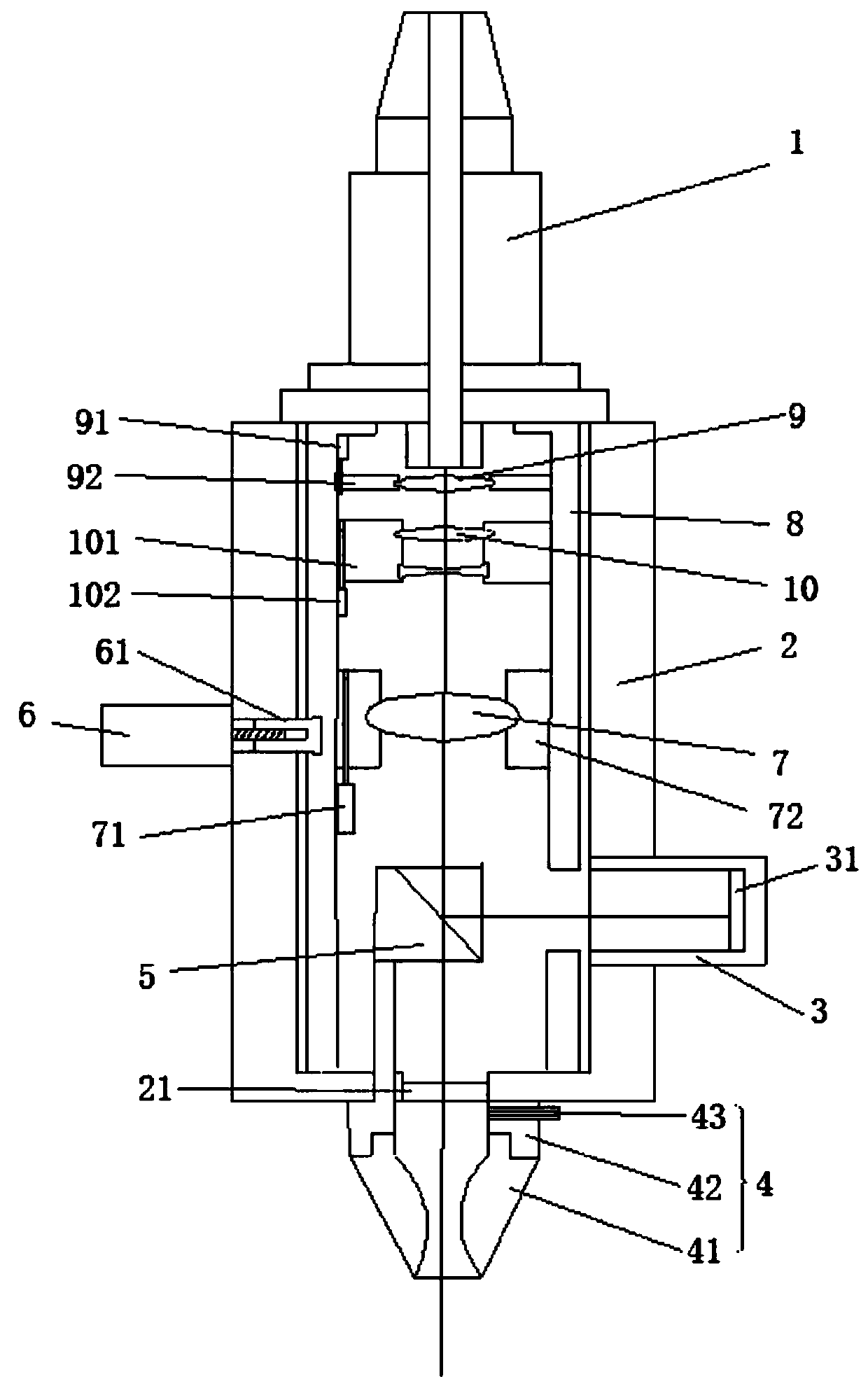
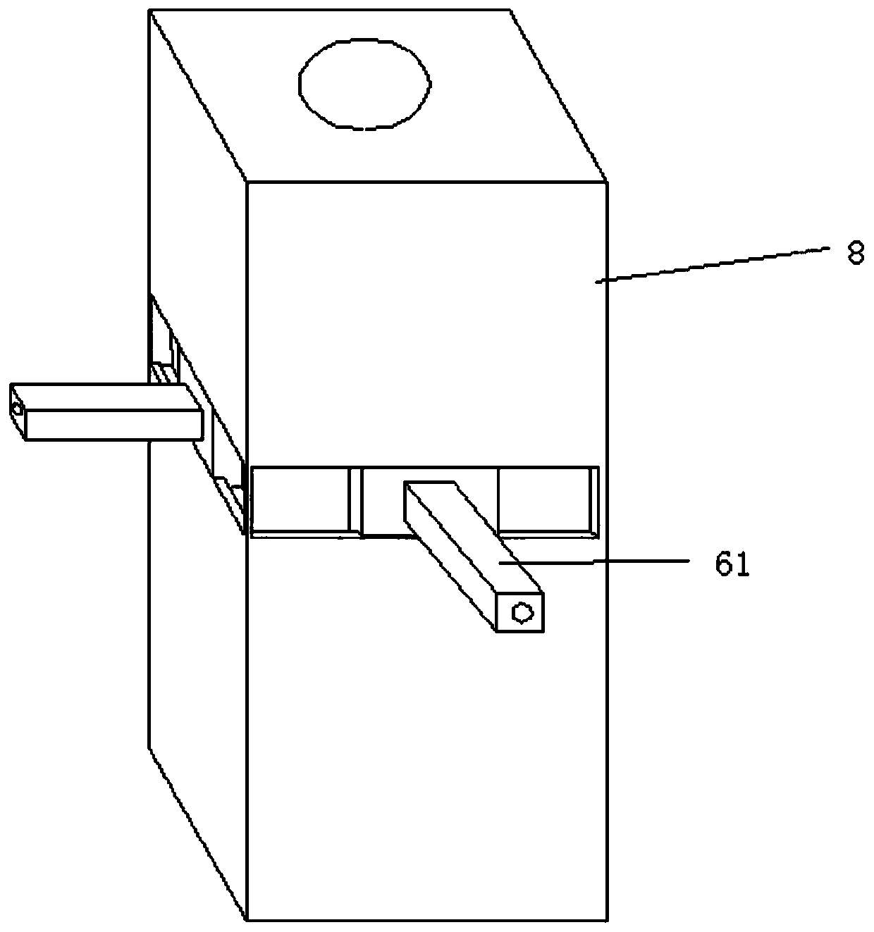
[0028] Please refer to figure 1 , figure 2 , image 3 , Figure 4 as well as Figure 5 ,in figure 1 A structural schematic diagram of a preferred embodiment of the laser head of the laser cutting machine provided by the present invention; figure 2 for figure 1 The schematic diagram of the internal structure of the laser head of the laser cutting machine shown; image 3 for figure 2 The frame and the structural schematic diagram of the slider are shown; Figure 4 for figure 2 The schematic diagram of the optical path of the converging lens group shown; Figure 5 for figure 2 Schematic diagram of the optical path of the zoom lens, beam splitter lens and light metering tube shown.

[0029] refer to figure 1 As shown, a laser head of a laser cutting machine includes a housing 2, the housing 2 is a cuboid structure, the housing 2 is provide...


PUM


Abstract

The invention provides a laser head of a laser cutting machine. The laser head comprises an optical fiber connector, a shell, a frame, a protective mirror, a nozzle, a linear motor, a sliding block, aphotometric cylinder, a beam splitter prism and a lens group; the optical fiber connector is cooperated with an optical fiber to connect the laser head with a laser generating device; a laser beam issplit by the beam splitter prism after passing through a zoom lens; most laser penetrates through the beam splitter prism, linearly penetrates through the protective mirror and is emitted out of thenozzle for laser cutting; a small amount of laser is reflected into the photometric cylinder through the beam splitter prism; a light sensing mechanism in the photometric cylinder senses the light irradiation position; and the beam splitter prism is connected with the nozzle; the positions of the transmitted laser and the reflected laser are synchronously changed along with change of the positionof the laser beam irradiated to the beam splitter prism, the movement of the frame is controlled according to the position information of the reflected laser, so that the position of the laser beam irradiated to the beam splitter prism is changed, and the transmitted laser can be always coaxial with the nozzle.

Description

technical field [0001] The invention relates to the field of laser cutting equipment, in particular to a laser head of a laser cutting machine. Background technique [0002] Laser cutting is the use of a focused high-power-density laser beam to irradiate the workpiece, so that the irradiated material is rapidly melted, vaporized, ablated or reached the ignition point, and at the same time, the molten material is blown away by the high-speed airflow coaxial with the beam, so that the workpiece can be cut. etc. purpose. [0003] The high-speed air flow coaxial with the beam is usually ejected from a nozzle arranged on the laser cutting head. At present, the nozzle used for laser cutting adopts a simple structure, that is, a gas channel in the shape of a tapered hole. Because the nozzle is generally made of red copper, it is small in size and is a vulnerable part that needs to be replaced frequently. However, in the actual production process, it is necessary to adjust the noz...

Claims


Application Information

Patent Timeline
IPC IPC(8): B23K26/38B23K26/064B23K26/142B23K26/046
CPCB23K26/046B23K26/0648B23K26/0652B23K26/38B23K26/064B23K26/142
Inventor 杨绪广于飞路世强韩小鹏
Owner JINAN BODOR LASER CO LTD
Why Eureka
Try Eureka