Technique for cement pouring in well cementing engineering

A process method and cement injection technology, which are applied in chemical instruments and methods, earthwork drilling, drilling composition and other directions, can solve the problems of low casing centering, poor cement-bonded stratum quality, and inability to perform adequate replacement, etc. To achieve the effect of effective isolation, improve the quality of cementation, and improve the efficiency of displacement

Inactive Publication Date: 2020-03-31
BEIJING BAOWO PETROLEUM TECH
View PDF5 Cites 2 Cited by
  • Summary
  • Abstract
  • Description
  • Claims
  • Application Information

AI Technical Summary

Problems solved by technology

At present, due to the unavoidable low centering degree of the casing in highly deviated wells or horizontal wells, the wide-side narrow-side effect occurs during the displacement process, and the mud cake remains on the wellbore wall to form a virtual mud cake, which makes it difficult to satisfy the wall shear stress theory (displacement Density of the fluid should be at least 10% higher than that of the displaced fluid, and its rheology should be at least 20% higher. The theoretical order of the rheological properties of the four slurries should be: tail slurry > collar slurry > spacer fluid > mud), so that full displacement cannot be performed , resulting in poor cement bonded formation quality

Method used


Image

  • Technique for cement pouring in well cementing engineering
  • Technique for cement pouring in well cementing engineering
  • Technique for cement pouring in well cementing engineering

Examples


preparation example Construction

[0035] The preparation process of the 1.30sg spacer is as follows:

[0036] Add 100 parts of water in the first mixer;

[0037] Add 7.5 parts of Naki Sakato.

[0038] Fully hydrated, the time is 40-48h;

[0039] Add 1.5 parts of thickener, which is produced by Chengdu Dedao Industrial Co., Ltd., code-named D1001;

[0040] Add 38 parts of barite;

[0041] Fully stir, wherein, the stirring speed is 8000-10000r / min, and the stirring time is 60s.

[0042] Complete the preparation of 1.30sg spacer solution.

[0043] Adopt above-mentioned process method to make the experimental data of spacer liquid as follows:

[0044] experimental project Experimental results density 1.30 Density difference between upper and lower pulp <0.02

[0045] The six-speed numbers are as follows:

[0046] Temp / ℃ / speed 600 300 200 100 6 3 56 92 60 45 32 7 5

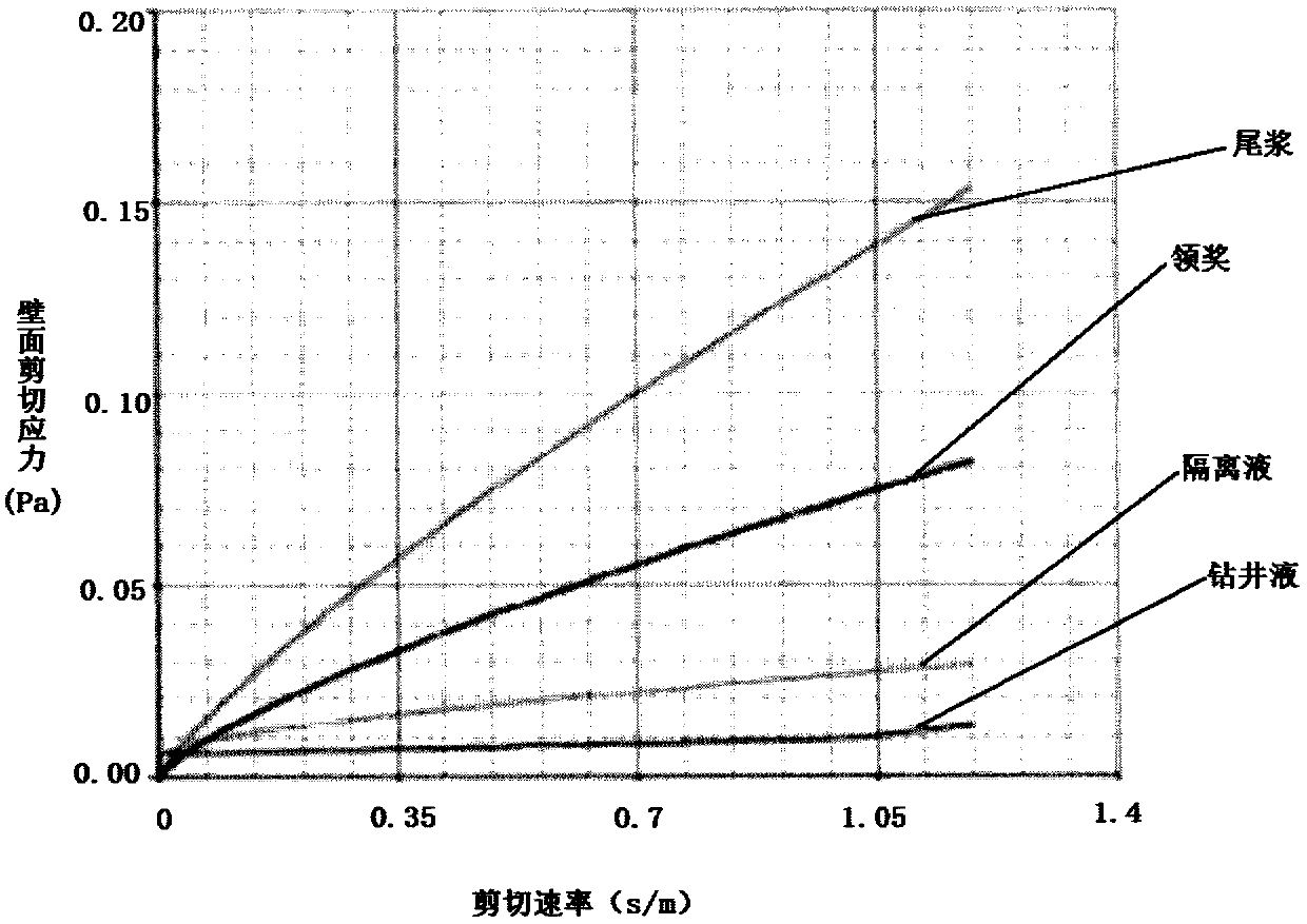
[0047] Based on the six-speed value of the 1.30sg spacer fluid circulating in the we...

Embodiment 1

[0086] Present embodiment 1 is the highly deviated well (oil well) that well depth is 2366m, and maximum well deviation is 79 °, and described well internal circulation temperature is 56 °, and used drilling fluid is the drilling fluid that density is less than 1.18sg, and average well diameter is 13in (inch), the casing diameter is 9.625in (inch), and the average annular cross section is 0.03867m 2 .

[0087] Step 1, run the casing in the wellbore;

[0088] Step 2. After the casing is run in, the drilling fluid is injected into the drilling fluid in a jacking cycle (generally 2 weeks), the displacement is slow and the pump pressure is stable from 0.38m 3 / min commission to 2.73m 3 / min, adjust the performance of the drilling fluid so that the viscosity of the funnel is less than 45Pa s, and the dynamic shear force is less than 5Pa;

[0089] Step 3. Inject spacer fluid: use a cement truck to inject 16m of spacer fluid 3 , its displacement is 0.7955m 3 / min;

[0090] Step...


PUM

PropertyMeasurementUnit
compressive strengthaaaaaaaaaa

Abstract

The invention discloses a technique for cement pouring in well cementing engineering. The technique comprises the steps that a casing is put into a well mouth; a spacer fluid with a density of 1.30sgis poured by pumping into the casing; a lower rubber plug is put down; head slurry and tail slurry are successively poured by pumping into the casing, wherein the head slurry is cement paste with a density of 1.45sg and the tail slurry is cement paste with a density of 1.75sg; an upper rubber plug is put down; a drilling liquid with a density under 1.18sg is poured from the casing for alternation,so the spacer fluid, the head slurry and the tail slurry can return upwards to a preset height in an annular space between outside of the casing and a well wall, wherein an annular returning speed ofthe spacer fluid, the head slurry and the tail slurry in the annular space is not lower than 0.21s / m; and the upper rubber plug is used for press collision and pressure stabilization, unloading is conducted, cementing is waited, and construction is finished. The technique disclosed by the invention has the beneficial effects that wall face shear stress theoretical conditions can be satisfied between the tail slurry, the head slurry and the spacer fluid at the same time; when a centralizing degree of the horizontal well casing with a large slope cannot reach standards, cement slurry displacement efficiency can be effectively increased; and gluing quality between cement and a stratum can be improved, and effective sealing can be realized.

Description

technical field [0001] The invention belongs to the technical field of oilfield well cementing engineering, and in particular relates to a cementing process in well cementing engineering. Background technique [0002] The cementing operation in the cementing engineering of oil and gas wells is the key process after the casing is run into the well. to the passage in the well. In the grouting operation, spacer fluid, leading slurry and tailing fluid are sequentially injected into the annular space between the outside of the casing and the well wall through the inner casing of the oil and gas well, and the remaining drilling fluid (mud) on the well wall is replace. At present, due to the unavoidable low centering degree of the casing in highly deviated wells or horizontal wells, the wide-side narrow-side effect occurs during the displacement process, and the mud cake remains on the wellbore wall to form a virtual mud cake, which makes it difficult to satisfy the wall shear st...

Claims


Application Information

Patent Timeline
Patent Type & Authority Applications(China)
IPC IPC(8): E21B33/13C09K8/40C09K8/46C04B28/02C04B28/00C04B111/70
CPCC04B28/001C04B28/02C04B2111/00724C04B2111/70C04B2201/20C04B2201/50C09K8/40C09K8/46E21B33/13C04B14/368C04B2103/44C04B18/146C04B2103/0068C04B2103/50
Inventor 范维旺范洪胜鄂晓旭
Owner BEIJING BAOWO PETROLEUM TECH
Why Eureka
Try Eureka