Grid plate design method of air bath device, grid plate, air bath device and photoetching machine
A design method and grid plate technology, applied in the field of photolithography, can solve problems such as large shape and size restrictions, increased pressure resistance of filters, and large filter size, so as to improve quality, reduce thickness, and ensure uniformity Effects on sex and stability
- Summary
- Abstract
- Description
- Claims
- Application Information
AI Technical Summary
Problems solved by technology
Method used
Image

Examples
Embodiment 2
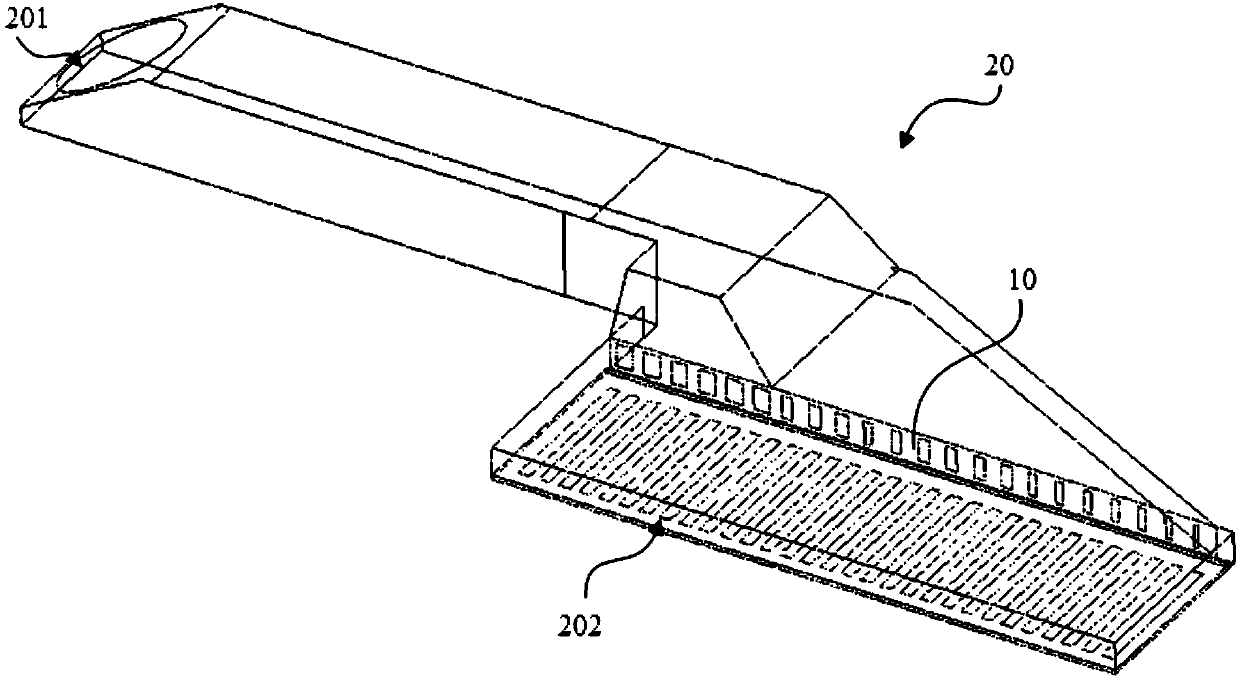
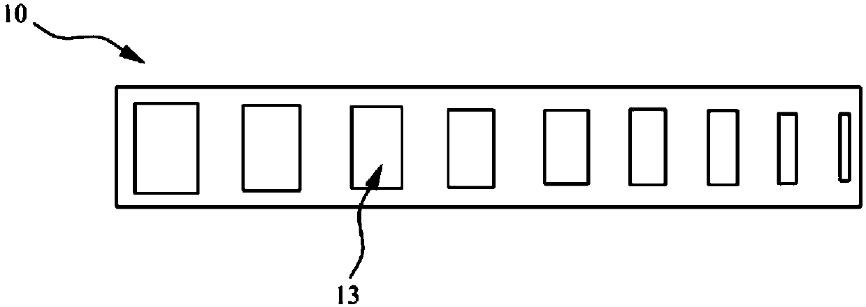
[0108] image 3 A schematic structural diagram of the grid plate 10 provided in this embodiment. Such as image 3 As shown, this embodiment provides a grid plate 10, which is designed and formed by using the grid plate design method of the first embodiment.
[0109] Specifically, the grid plate 10 is a rectangular plate structure, on which a plurality of grids 13 are arranged, and the number of the grids 13 is the same as the number of the grids 13 in step S1 of the first embodiment, and the number of each grid 13 The ventilation area is the optimal ventilation area in step S5 of the first embodiment, and the position of each grid 13 is the same as the position of the grid 13 calculated and obtained in the first embodiment.
[0110] The grid plate 10 provided in this embodiment, because it is a non-uniform grid plate 10 obtained by adopting the grid plate design method of the first embodiment, can achieve better homogenization of the airflow in the air bath device, Improve ...
Embodiment 3
[0115] Figure 5 A schematic structural diagram of the grid plate 10 provided in this embodiment. Such as Figure 5 As shown, this embodiment provides an adjustable grid plate 10, which can adopt the grid plate design method provided in the first embodiment, and assist its own adjustment function, so that the grid plate 10 can be adjusted from the first embodiment. The initial design parameters are adjusted to the optimal design parameters in Embodiment 1 to obtain a non-uniform grid plate 10 design.
[0116] Specifically, such as Figure 5 As shown, the grid plate 10 provided in this embodiment includes a main body 1 and a grid adjustment assembly 2. A plurality of grids 13 are provided on the main body 1. The number, position and initial ventilation area of the grids 13 are the same as those in the first embodiment. The parameters in step S1 are the same. The number and position of the adjustment components correspond to each grid 13 one by one, and the adjustment comp...
Embodiment 4
[0126] Such as Image 6 As shown, this embodiment provides an adjustable grid plate 10, which can adopt the grid plate design method provided in the first embodiment, and assist its own adjustment function, so that the grid plate 10 can be adjusted from the first embodiment. The initial design parameters are adjusted to the optimal design parameters in Embodiment 1 to obtain a non-uniform grid plate 10 design.
[0127] Specifically, such as Image 6 As shown, the grid plate 10 provided in this embodiment includes a main body 1 and a grid adjustment assembly 2. The main body 1 is provided with a plurality of grids 13, and the number and position of the adjustment components correspond to each grid 13 one by one. And the adjusting component can adjust the ventilation area of the corresponding grid 13 to the optimal ventilation area.
[0128] In this embodiment, the body 1 has a hexahedral structure, and the length direction of the body 1 is arranged along the width direction...
PUM
 Abstract
Description
Claims
Application Information
 - R&D
- Intellectual Property
- Life Sciences
- Materials
- Tech Scout
- Unparalleled Data Quality
- Higher Quality Content
- 60% Fewer Hallucinations
Browse by: Latest US Patents, China's latest patents, Technical Efficacy Thesaurus, Application Domain, Technology Topic, Popular Technical Reports.
© 2025 PatSnap. All rights reserved.Legal|Privacy policy|Modern Slavery Act Transparency Statement|Sitemap|About US| Contact US: help@patsnap.com