Forming method of hard alloy bar with spiral hole

A technology of cemented carbide rods and forming methods, applied in the field of cemented carbide, which can solve the problems of complex structure and inability to produce porous cemented carbide rods, and achieve the effect of stable helix angle and stable diameter

Inactive Publication Date: 2020-04-03
HUNAN UNIV OF TECH
View PDF8 Cites 2 Cited by
  • Summary
  • Abstract
  • Description
  • Claims
  • Application Information

AI Technical Summary

Problems solved by technology

The Chinese patent with the publication number CN203061591U discloses a device for producing alloy rods with spiral inner cooling holes. The alloy rods with spiral inner cooling holes are produced by setting the inner hole core beam support, but it can only produce hard steel rods with single holes. Alloy rods cannot produce porous cemented carbide rods, and the structure is complex

Method used


Image

  • Forming method of hard alloy bar with spiral hole
  • Forming method of hard alloy bar with spiral hole
  • Forming method of hard alloy bar with spiral hole

Examples


Embodiment 1

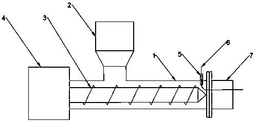
[0029] like figure 1 As shown, this embodiment provides a screw extrusion molding device for cemented carbide rods with spiral holes, including a screw extruder and a die head 7, and the die head used in this embodiment is a rotary die head. The screw extruder includes a driving motor 4 and a barrel 1. The driving motor 4 is located at one end of the barrel 1. The barrel 1 is provided with a feeding hopper 2 used as a feeding port, and a rotary die 7 is installed on the discharging port. The barrel 1 is provided with a screw 3 , the screw 3 is in clearance fit with the barrel 1 , and the screw 3 is connected with the drive motor 4 .

[0030] In this embodiment, the end of the extruder is provided with a rotary die 7 having the same shape as the cemented carbide rod, a through hole 5 is provided on the barrel 1 of the extruder, and a polymer wire 6 is introduced into the through hole ; Die head 7 is connected with the extruder with a guide hole; the polymer wire 6 passes throu...

Embodiment 2

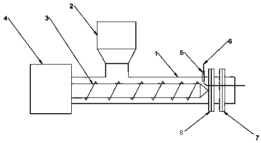
[0032] like figure 2 As shown, this embodiment refers to Embodiment 1, and provides a screw extrusion molding device for cemented carbide rods with spiral holes. In this embodiment, a shaping die is also provided between the rotary die 7 and the extruder. The head 8, the sizing die 8 is provided with a positioning hole, and the position of the positioning hole on the sizing die 8 corresponds to the position of the guide hole of the rotating die 7. The sizing die 8 is fixedly connected to the extruder, and the rotating die 7 is connected to the sizing die 8 .

[0033] In this embodiment, a through hole 5 is provided on the barrel 1, a positioning hole is provided on the sizing die 8, and a guide hole is provided on the rotating die 7. The positioning holes correspond to the positions of the guide holes, and the polymer wires 6 are arranged in sequence. Pass through the through hole 5, the positioning hole and the guide hole. The number of through holes 5, positioning holes a...

Embodiment 3

[0036] This embodiment provides a process for forming a cemented carbide bar with a spiral hole, the number of spiral holes is one, and the following steps are included:

[0037] Carbide rods were prepared on the extruder provided in Example 1. The end of the extruder was provided with a rotating die, the rod was extruded into the die, and a polymer was introduced from the through hole of the extruder. Rotating the die head, the polymer wire passes through the through hole on the barrel and the guide hole on the rotary die head in turn, and is fixed at the corresponding position of the cemented carbide section; when the die head is rotated, the polymer wire is driven by the die head at the same speed. Rotate to obtain a polymer wire with a helix angle in the cemented carbide; heat the cemented carbide rod to above 1000 ° C, the polymer wire is decomposed, and a cemented carbide rod with a helical hole is obtained.


PUM


Abstract

The invention discloses a forming method of a hard alloy bar with a spiral hole. According to the forming method, hard alloy powders and a polymer wire are used as raw materials, a hard alloy blank with the polymer wire is formed after the raw materials are extruded and molded through a screw, and the hard alloy bar with the spiral hole is obtained after the hard alloy blank is sintered. Accordingto the forming method, through cooperation of a screw extruder and a rotary die head, stable and continuous production of the hard alloy bars is achieved, and the diameter and number of the spiral holes on the hard alloy bar can be controlled through adjusting the diameter and the number of thread lines, so that it is ensured that the diameter and the spiral lifting angle of the spiral hole are stable.

Description

technical field [0001] The present invention relates to the technical field of cemented carbide, and more particularly, to a method for forming cemented carbide rods with spiral holes. Background technique [0002] Carbide tools, especially carbide drills, are usually made of carbide rods to form a helical cutter head. When the tool is drilling, in order to reduce the temperature, it is necessary to inject water and coolant while drilling. The addition of screw grooves will hinder the discharge of chips and slag, thereby reducing machining efficiency and tool life. [0003] Carbide milling tools with internal spiral cooling holes can use internal cooling, which can speed up the cooling speed and chip removal speed under the action of a certain pressure coolant or lubricant, thereby improving the speed, machining accuracy and service life of the milling tool. The Chinese patent with publication number CN203061591U discloses a device for producing alloy bars with spiral inner...

Claims


Application Information

Patent Timeline
Patent Type & Authority Applications(China)
IPC IPC(8): B22F5/10B22F3/20
CPCB22F3/20B22F5/10
Inventor 曾广胜
Owner HUNAN UNIV OF TECH
Why Eureka
Try Eureka