
Manipulator fixture and robot

A technology of manipulators and fixtures, applied in the direction of manipulators, program-controlled manipulators, chucks, etc., can solve the problems that the manipulator is difficult to accurately position the product, the manipulator positioning is complicated and troublesome, and the clamping efficiency is difficult to achieve, so as to improve the level of automatic operation, The effect of safe gripping, easy manufacture and use

Pending Publication Date: 2020-04-03
SHENZHEN SUNSHINE LASER & ELECTRONICS TECH CO LTD
View PDF0 Cites 4 Cited by
  • Summary
  • Abstract
  • Description
  • Claims
  • Application Information

AI Technical Summary

Problems solved by technology

The fixture of this type of six-axis robot relies on the control program of the manipulator to position itself, but when the product size or position is different, the positioning of the manipulator will become complicated and troublesome
When the size or position of the product to be clamped twice is different, it is difficult for the manipulator to accurately position the product, which leads to the problem of inaccurate clamping, and it is also difficult to improve the clamping efficiency, and there is even a hidden danger of damage to the product

Method used


Image

  • Manipulator fixture and robot
  • Manipulator fixture and robot
  • Manipulator fixture and robot

Examples


Embodiment Construction

[0024] Embodiments of the present invention will be described in detail below. It should be emphasized that the following description is only exemplary and not intended to limit the scope of the invention and its application.

[0025] It should be noted that when an element is referred to as being “fixed” or “disposed on” another element, it may be directly on the other element or be indirectly on the other element. When an element is referred to as being "connected to" another element, it can be directly connected to the other element or indirectly connected to the other element. In addition, connection may be for both a fixed function and a circuit / signal communication function.

[0026] It is to be understood that the terms "length", "width", "top", "bottom", "front", "rear", "left", "right", "vertical", "horizontal", "top" , "bottom", "inner", "outer" and other indicated orientations or positional relationships are based on the orientations or positional relationships sh...


PUM


Abstract

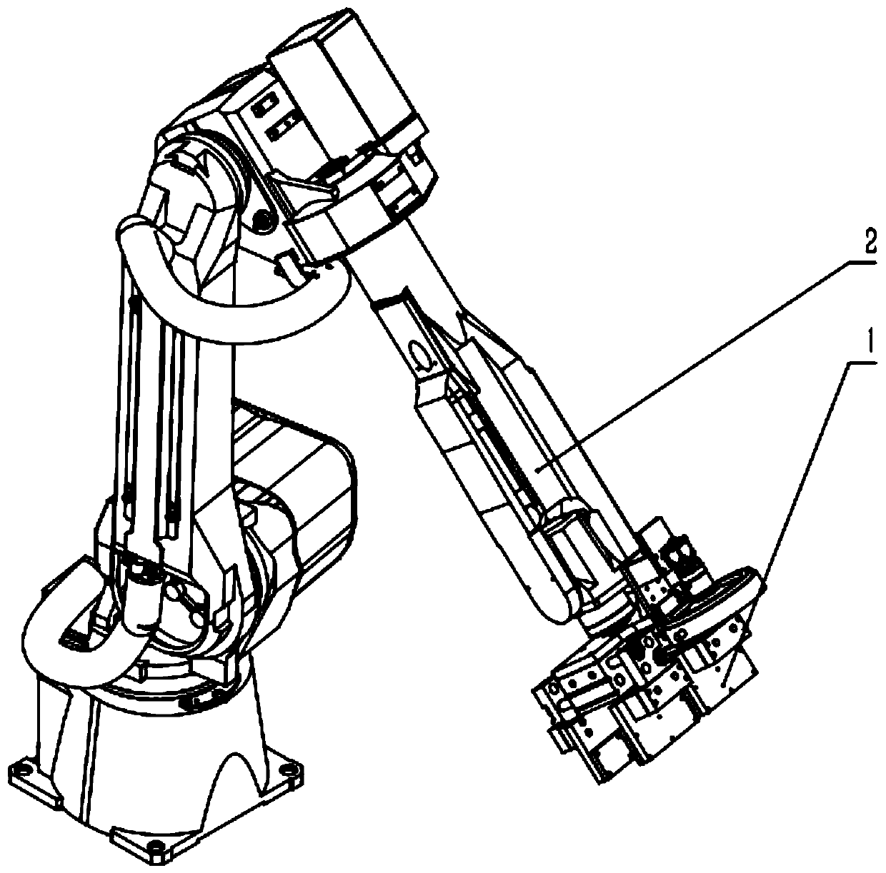
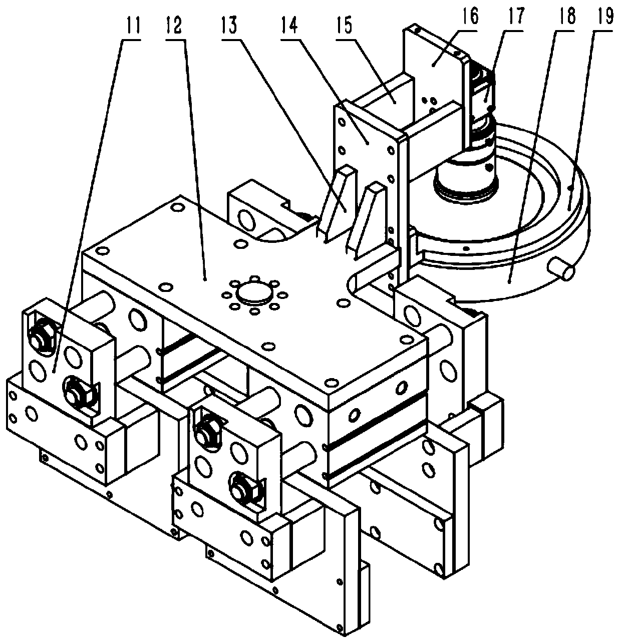
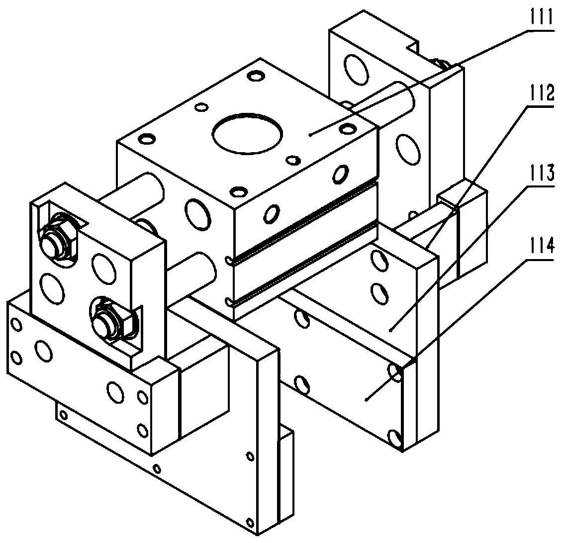
The invention discloses a manipulator fixture and a robot. The manipulator fixture comprises a clamping claw installation mechanism, a clamping claw, a visual position compensation system and a control unit. The clamping claw installation mechanism and the visual position compensation system are installed on a manipulator. The clamping claw is installed on the clamping claw installation mechanism.The visual position compensation system and the manipulator are connected with the control unit respectively. The visual position compensation system is used to shoot an image of an object to be clamped and transmits the image to the control unit while the manipulator enables the clamping claw to clamp the object. The control unit is used to position the clamping claw relative to the object to beclamped according to the images shot by the visual position compensation system, and controls the manipulator to compensate for the moving position of the clamping claw according to the situation ofpositioning.

Description

technical field [0001] The present invention relates to robotic devices, in particular to manipulator grippers and robots. Background technique [0002] Joint robot is one of the more common forms of industrial robots in the industrial field. It is suitable for mechanical automation operations in various industrial fields, such as: automatic assembly, painting, handling, welding and other work. Among them, the more common and widely used is the six-axis robot, which provides higher production motion flexibility. The fixture of this type of six-axis robot relies on the control program of the manipulator to position itself, but when the product size or position is different, the positioning of the manipulator will become complicated and troublesome. When the size or position of the product to be clamped twice is different, it is difficult for the manipulator to accurately position the product, which leads to the problem of inaccurate clamping, it is also difficult to improve ...

Claims


Application Information

Patent Timeline
IPC IPC(8): B25J15/02B25J15/08B25J9/16
CPCB25J15/0253B25J15/08B25J9/1697B25J9/1602
Inventor 王轩朱远福马建立王东
Owner SHENZHEN SUNSHINE LASER & ELECTRONICS TECH CO LTD
Learn More