Electro-pneumatic brake control device and brake control system

A technology of electro-pneumatic braking and control devices, applied in the direction of braking transmission devices, brakes, pneumatic brakes, etc., can solve the problems of rolling stock and line damage, endangering driving safety, broken hooks, etc., to reduce damage and reduce impact force , improve the effect of consistency

Pending Publication Date: 2020-04-03
MEISHAN CRRC BRAKE SCI & TECH CO LTD
View PDF0 Cites 6 Cited by
  • Summary
  • Abstract
  • Description
  • Claims
  • Application Information

AI Technical Summary

Problems solved by technology

The longer and heavier the train, the faster the braking force of the vehicle will rise, and the greater the impact force will be. If it exceeds a certain t

Method used


Image

  • Electro-pneumatic brake control device and brake control system
  • Electro-pneumatic brake control device and brake control system
  • Electro-pneumatic brake control device and brake control system

Examples


Example Embodiment

[0026] Example 1:

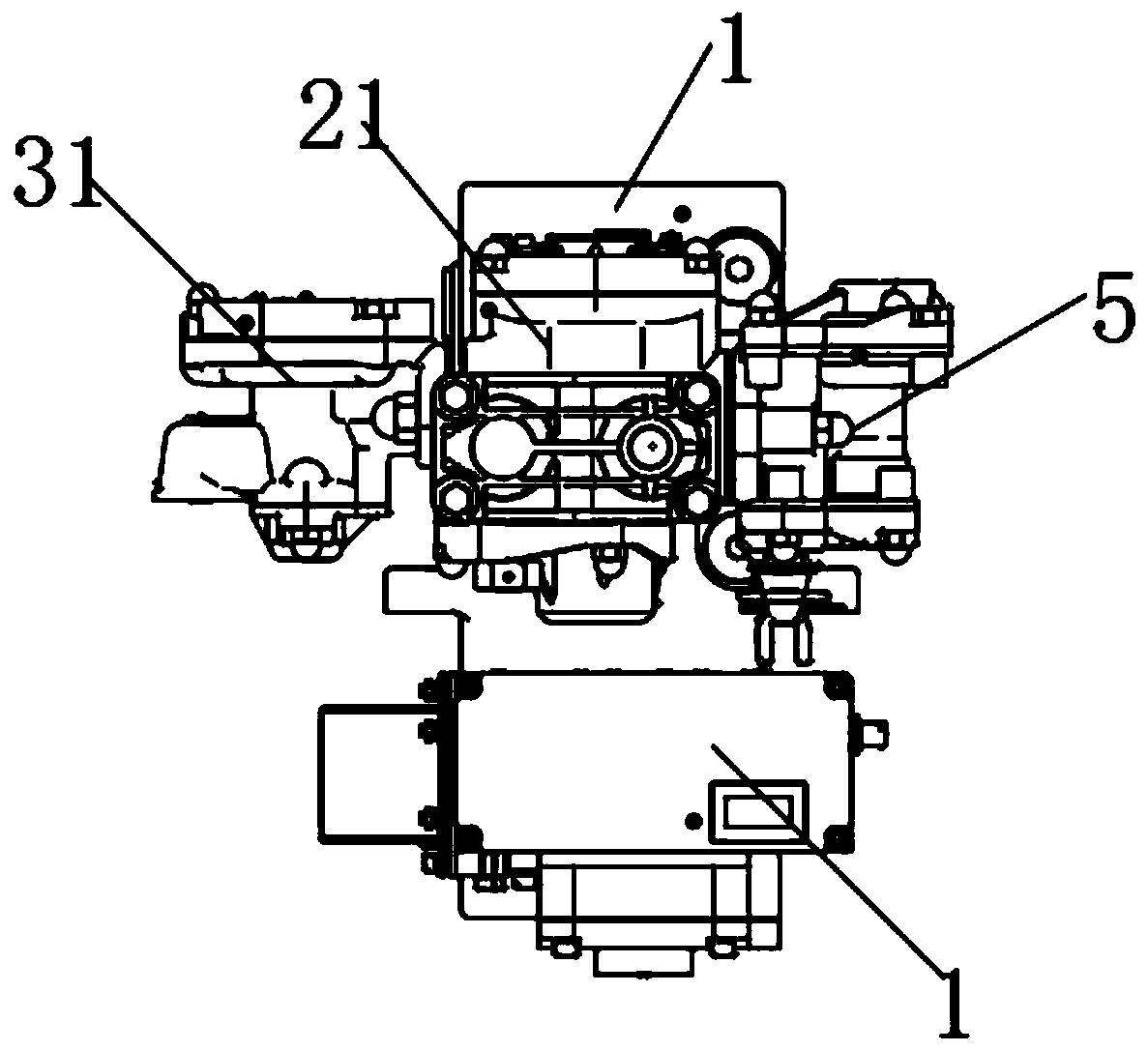
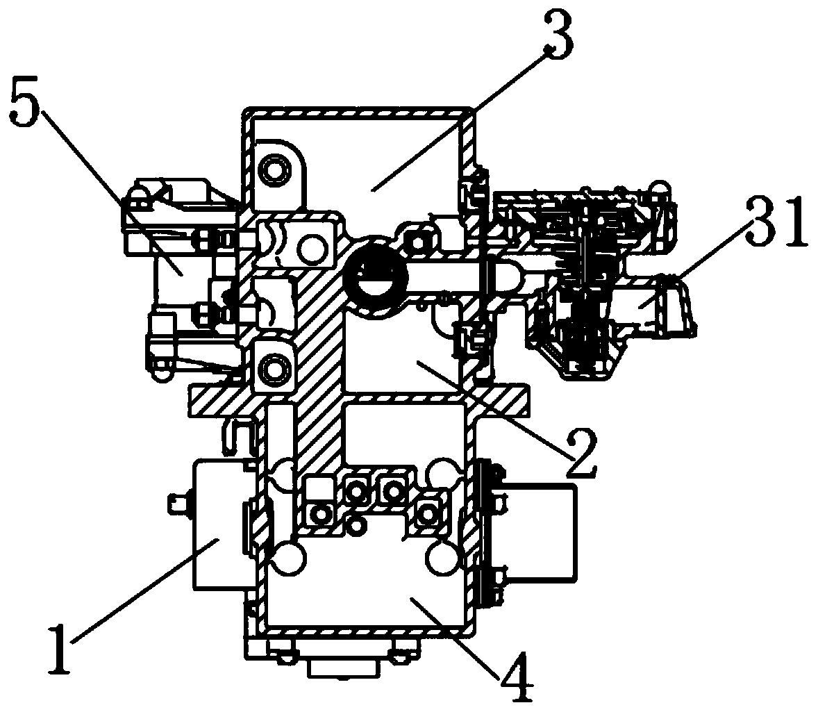
[0027] Such as figure 1 , figure 2 , image 3 As shown, in this embodiment, a control device for electro-pneumatic braking includes an intermediate body and a control unit installed on the intermediate body;

[0028] The intermediate body includes a mounting seat 1 and a pre-control room 4 arranged in the mounting seat 1, and the control unit is in communication with the pre-control room 4;

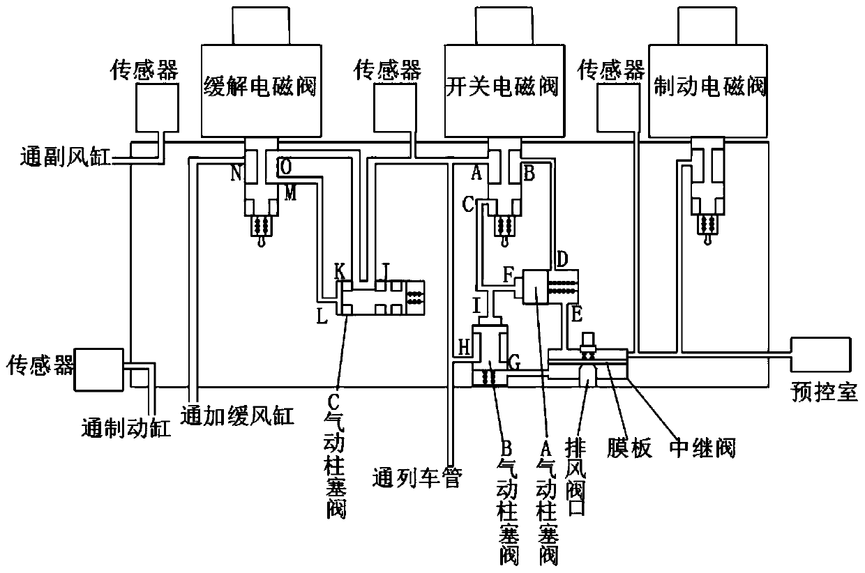
[0029] The control unit includes an on-off solenoid valve that communicates with the train pipe through port C, an A pneumatic plunger valve that communicates with port B of an on-off solenoid valve A through port D, and a center connecting the space on the diaphragm with port E of the pneumatic plunger valve A. The relay valve and the pre-control chamber arranged in the intermediate body and communicating with the upper space on the diaphragm; the lower space of the relay valve diaphragm is connected with the train pipe; the F port of the A pneumatic plunger valve is conne...

Example Embodiment

[0042] Example 2:

[0043] On the basis of the above embodiment, in this embodiment, the lower space of the relay valve diaphragm is connected with the G port of the B pneumatic plunger valve, and the H port of the B pneumatic plunger valve is connected with the train pipe. The I port of the B pneumatic plunger valve is connected to the F port of the A pneumatic plunger valve.

[0044] When the on-off solenoid valve loses power, the B pneumatic plunger valve is used to cut off the space between the train pipe and the lower side of the diaphragm to prevent the exhaust valve from being tightly sealed and causing the train pipe to exhaust.

[0045] When the switch solenoid valve is energized, the A port is connected to the C port, and the pressure air of the train pipe enters the B pneumatic plunger valve through the C port and the I port to push the plunger in the B pneumatic plunger valve to move, making the H port Connect with G port, even if the space under the diaphragm is connect...

Example Embodiment

[0046] Example 3:

[0047] On the basis of the foregoing embodiment, in this embodiment, the outlet is a brake solenoid valve communicating with the air path between the relay valve and the pre-control chamber. Using the solenoid valve as the discharge outlet of the pressure air in the pre-control chamber can also realize the function of remote electronic control, thereby improving the response speed of the control and improving the braking efficiency. In this embodiment, the air path between the relay valve and the pre-control chamber communicates with a sensor. The use of sensors is conducive to real-time monitoring of pressure changes in the pre-control room, which is conducive to real-time control of pressure changes in the pre-control room and improve control accuracy.


PUM


Abstract

The invention discloses an electro-pneumatic brake control device and a brake control system. The electro-pneumatic brake control device comprises a middle body and a control unit. The middle body comprises a mounting base and a pre-control chamber, and the control unit is communicated with the pre-control chamber; the control unit comprises a switch electromagnetic valve, a pneumatic plunger valve A, a relay valve and a pre-control chamber; the lower side space of a relay valve diaphragm plate is communicated with a train pipe; a port F of the pneumatic plunger valve A is communicated with aport C of the switch electromagnetic valve A; the switch electromagnetic valve is connected with a control module, and the control module is connected with a communication module. The beneficial effects of the invention are that: according to the scheme, the switch electromagnetic valve is used for executing electric control signals to enable the train pipe of the middle-rear vehicle of the trainto follow the front vehicle as soon as possible, the consistency of the change of the braking force of the train is improved, the impact force between vehicles in the train is reduced, damage to locomotives and lines in the train braking process is reduced, and the controllability and application safety of the train are improved.

Description

technical field [0001] The invention relates to the technical field of train braking, in particular to a control device for electropneumatic braking and a braking control system. Background technique [0002] Traditional railway vehicles, especially freight vehicles, mainly use the air brake system, and use a train tube that runs through the whole train to control the braking and relief of each vehicle by controlling the pressure change of the train tube. The speed (wave speed) of the rear transmission is limited and will not exceed the speed of sound, so that the time at which vehicles at different positions in the train receive the driver's control signal is inconsistent, and the reception of the control signal and response control of the rear vehicles in the train will be delayed. Seriously, the connection between the train vehicles is a hinged structure with a gap, and the asynchronous braking action between the vehicles will generate a pulling or squeezing impact at the...

Claims


Application Information

Patent Timeline
IPC IPC(8): B60T13/66B60T13/68B61H11/06
CPCB60T13/662B60T13/683B61H11/06
Inventor 刘亚梅蒋勇朱宇刘文军杨金龙宋志勇唐琦
Owner MEISHAN CRRC BRAKE SCI & TECH CO LTD
Why Eureka
Try Eureka