
Mounting device and mounting method for steel casing of underwater drilling cast-in-place pile

A technology of bored piles and installation devices, which is applied in the direction of sheet pile walls, buildings, and foundation structure engineering, and can solve the overturning damage of underwater bored pile foundations and their superstructures, and the slippage of underwater bored pile foundations. It can avoid the risks of strength softening and liquefaction catastrophe, save construction costs, and broaden the application prospects of projects.

Pending Publication Date: 2020-04-03
ZHEJIANG UNIV CITY COLLEGE
View PDF0 Cites 1 Cited by
  • Summary
  • Abstract
  • Description
  • Claims
  • Application Information

AI Technical Summary

Problems solved by technology

At present, the common installation of the steel casing of the underwater bored pile is to penetrate into the underwater soft soil by means of shock vibration or hammering. This kind of traditional steel casing installation method will disturb the soft soil around the steel casing. Destroy the microstructure of the soil and soften its strength; on the other hand, it will also form super-static pore water pressure in the soft soil around the steel casing. If the accumulated super-static pore water pressure does not dissipate in time, it will make the underwater The liquefaction damage of the soil around the bored pile foundation may cause slippage or fracture of the underwater bored pile foundation, and even cause the overall overturning damage of the underwater bored pile foundation and its superstructure, resulting in Casualties and huge property losses

Method used


Image

  • Mounting device and mounting method for steel casing of underwater drilling cast-in-place pile
  • Mounting device and mounting method for steel casing of underwater drilling cast-in-place pile
  • Mounting device and mounting method for steel casing of underwater drilling cast-in-place pile

Examples


Embodiment Construction

[0040] The present invention will be described in further detail below in conjunction with the accompanying drawings and embodiments.

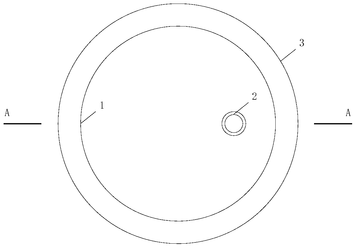
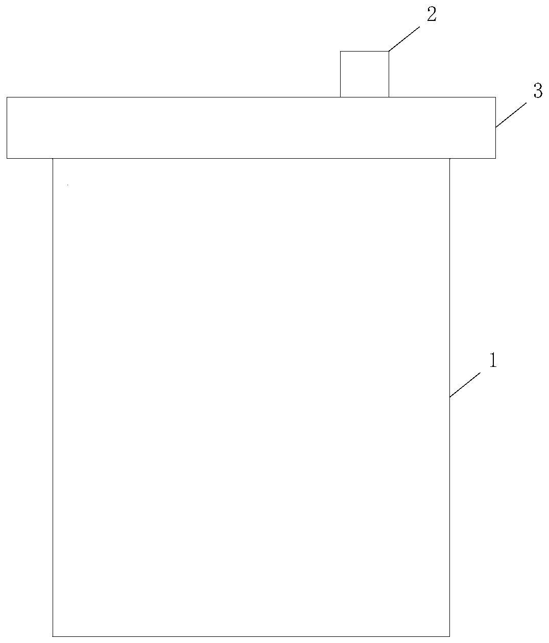
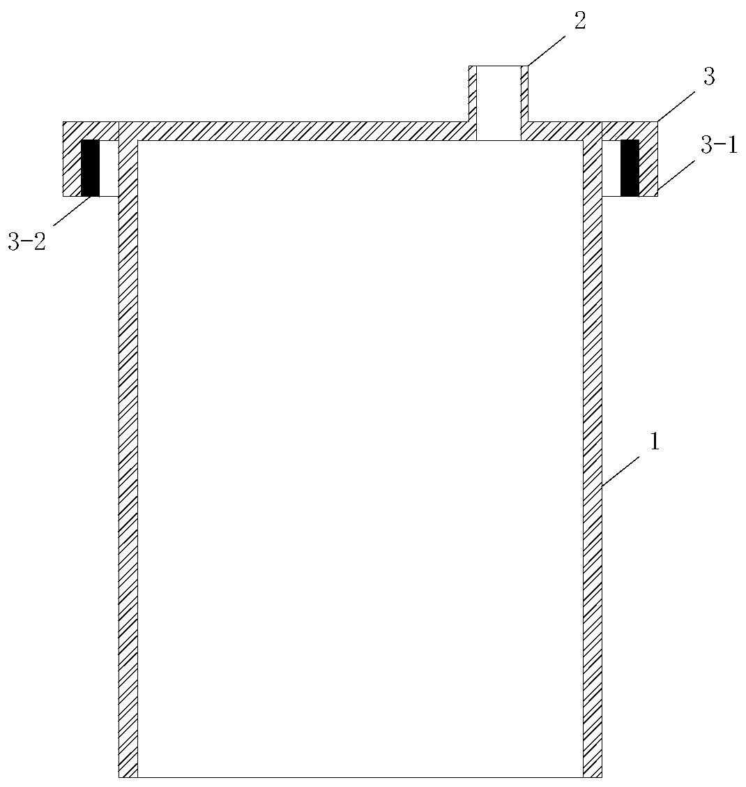
[0041] Such as Figure 1-3 As shown, a steel casing installation device for underwater drilled cast-in-place piles provided by this embodiment includes a suction barrel 1, a water passage / air hole 2 and a magnetic installation top cap 3; the suction barrel 1 is a steel barrel with an open bottom ; The water flow / air hole 2 is located at the top of the suction bucket 1 and communicates with the inside of the suction bucket 1; the magnetic installation top cap 3 is composed of an annular top hat 3-1 and an electromagnet 3-2; the magnetic installation top hat 3 The annular top cap 3-1 is fixedly connected to the top of the suction bucket 1 by circumferential welding; a number of paired and fan-shaped electromagnets 3-2 are installed on the lateral inner wall of the annular top cap 3-1;

[0042] The outer diameter of the suction barrel 1 is small...


PUM


Abstract

The invention discloses a mounting device and a mounting method for a steel casing of an underwater drilling cast-in-place pile. The mounting device comprises a suction bucket, a water / gas passing hole and a magnetic mounting top cap, wherein the water / gas passing hole is formed in the top of the suction bucket; the magnetic mounting top cap comprises an annular top cap and an electromagnet; the steel casing of the underwater cast-in-place pile is mounted by adopting a suction bucket technology; the steel casing penetrates through soil by vacuumizing the suction bucket of the mounting device,gas is injected in the suction bucket under high pressure and the mounting device is removed by adopting a hoisting method of a crane, the soil to be excavated on the inner side of the steel casing isonly disturbed in the mounting process, the soil at the periphery of the steel casing is not disturbed, and the liquidation risk in the construction period of the soil at the periphery of the underground drilling cast-in-pile foundation is effectively reduced; and the soil in the suction bucket is damaged in the dismantling process of the mounting device, so that the subsequent penetration of thesteel casing is facilitated, the construction period is beneficially shortened, and the construction cost is reduced. The mounting method is safe and reliable, and convenient and quick, and has a wide engineering application prospect.

Description

technical field [0001] The invention relates to the technical field of underwater bored cast-in-situ pile foundations, in particular to a steel casing installation device and method for underwater bored cast-in-place piles. Background technique [0002] With the rapid advancement of my country's urbanization process, a large number of cross-river / river bridges, sea-crossing bridges, river / river roads, coastal roads, and a series of water (river / river or sea) viewing platforms and other engineering projects have emerged. Pile-like foundations (especially underwater bored pile foundations) have played an important role in the smooth construction and normal operation of the above-mentioned projects. [0003] Soft soil with large porosity, low shear strength, high sensitivity and easy to be disturbed is widely distributed on the alluvial plains of rivers, river estuaries and continental shelves. In such soft soils, underwater bored piles are usually constructed. The steel casing...

Claims


Application Information

Patent Timeline
Patent Type & Authority Applications(China)
IPC IPC(8): E02D5/68E02D7/26
CPCE02D5/68E02D7/26Y02A20/204
Inventor 章丽莎魏骁魏纲张世民魏新江邢丽崔允亮
Owner ZHEJIANG UNIV CITY COLLEGE
Learn More