Distributed liquid temperature sensor based on fiber bragg grating

A fiber grating, liquid temperature technology, applied to thermometers, thermometers, instruments and other directions with physical/chemical changes, can solve the problems of complex operation, difficult implementation, can not completely isolate the grating force, etc., to achieve simple measurement structure, long-term good stability

Inactive Publication Date: 2020-04-03
WUHAN UNIV OF TECH
View PDF7 Cites 9 Cited by
  • Summary
  • Abstract
  • Description
  • Claims
  • Application Information

AI Technical Summary

Problems solved by technology

[0003] Due to the low sensitivity coefficient of fiber grating to temperature and the cross-sensitivity effect of temperature and strain, it is difficult to directly apply it to the temperature measurement of actual engineering.
Chinese patent CN106525277B uses a pure optical fiber and a grating segment to be coupled in a capillary with a matching inner diameter. There is a certain gap between the end of the grid section and the end face of the optical fiber, and the end face of the grating segment and the end face of the optical fiber are ground at an appropriate angle. The inclined planes are parallel and the interval is set. value, two sections of optical fiber are fixed by welding or gluing at both ends of the capillary to form a temperature sensing head, and a gap is left between the grating and the optical fiber to ensure that the grating is in a free state and ensure that the grating sensing process is not subject to temperature-stress Cross-sensitivity, but this method needs to cut the optical fiber, the operation is complicated, the implementation is difficult, and it leads to large optical loss, and the number of gratings in series is limited
[0004] In summary, the existing temperature sensors have one or more of the disadvantages of complex operation, large optical loss, inability to completely isolate the external force of the grating, and affecting accuracy.

Method used


Image

  • Distributed liquid temperature sensor based on fiber bragg grating
  • Distributed liquid temperature sensor based on fiber bragg grating
  • Distributed liquid temperature sensor based on fiber bragg grating

Examples


Embodiment Construction

[0021] In order to make the object, technical solution and advantages of the present invention clearer, the present invention will be further described in detail below in conjunction with the accompanying drawings and embodiments. It should be understood that the specific embodiments described here are only used to explain the present invention, not to limit the present invention.

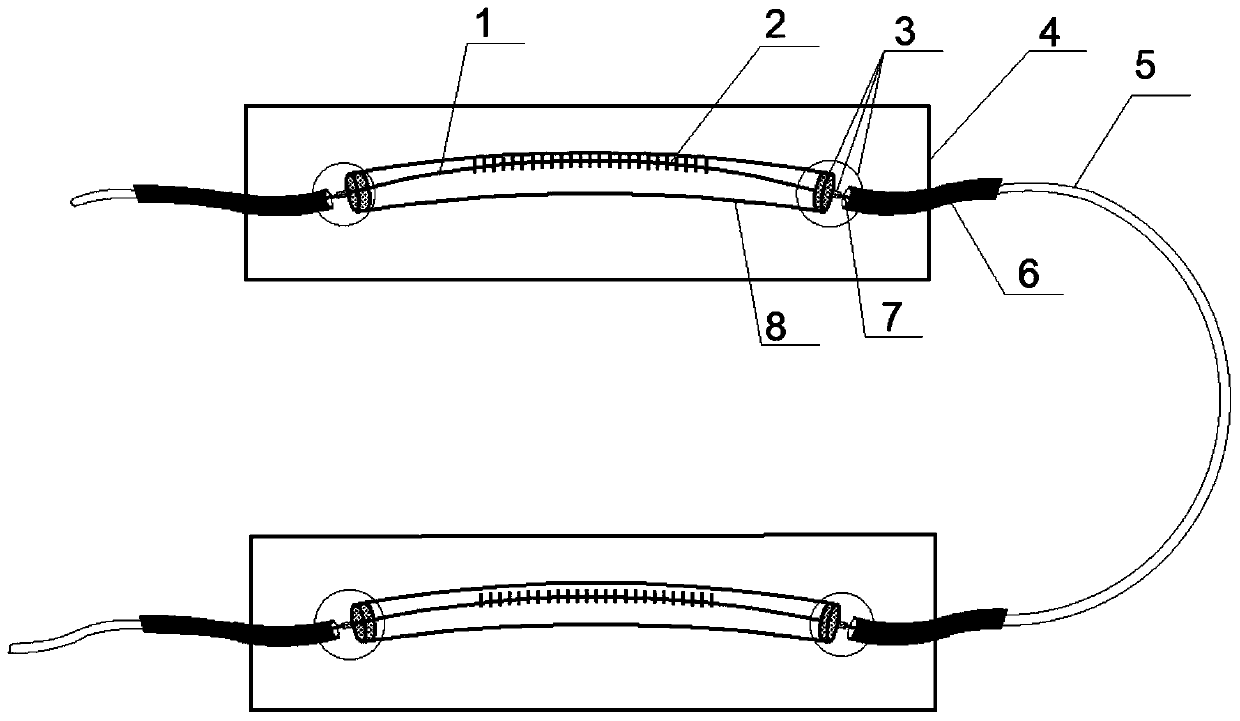
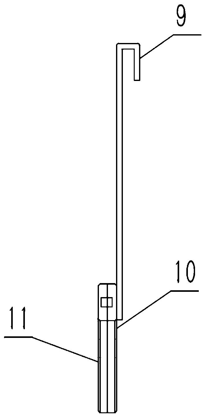
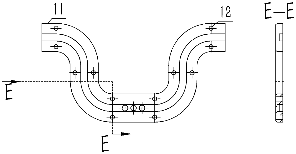
[0022] In the embodiment of the present invention, such as figure 1 , 2 As shown in , 3, a distributed liquid temperature sensor based on optical fiber gratings is provided, including outer protective shells 10, 11, external hooks 9, temperature measuring optical fiber gratings 1, stainless steel capillary tubes 8, substrate 4, and corrosion-resistant heat shrinkable tubes 5 , Fiber jumper 6. The temperature-measuring fiber grating 1 passes through the curved stainless steel capillary 8 and is not parallel to the axis of the capillary tube. The temperature-measuring fiber grating 1 is respectivel...


PUM


Abstract

The invention discloses a distributed liquid temperature sensor based on a fiber bragg grating. The sensor comprises a temperature measurement fiber grating, a stainless steel capillary tube, a substrate and a heat shrink tube, optical fiber jumper, the fiber bragg grating passes through the bent capillary tube after the coating layer is removed; the axis of the capillary steel pipe is not parallel; two ends of the stainless steel capillary tube respectively fix the optical fiber in the central area of the substrate through adhesives, the optical fiber area covered by the adhesives is not provided with a coating layer, and through the above packaging, the fiber bragg grating is ensured to resist external tension and optical fiber elongation caused by thermal expansion and cold contractionof the capillary tube, and the influence of thermal stress is isolated. The distributed liquid temperature sensor based on the fiber bragg grating has the advantages of being simple in structure, firmin installation and convenient to assemble and disassemble. The device has the characteristics of wide measurement range, high measurement precision and distributed measurement in function; and electromagnetic interference resistance and chemical corrosion resistance can be realized.

Description

technical field [0001] The invention belongs to the technical field of temperature detection, and in particular relates to a distributed liquid temperature sensor based on an optical fiber grating. Background technique [0002] Temperature is a physical quantity that characterizes the degree of coldness or heat of an object. It is one of the seven basic physical quantities in the International System of Units. It is closely related to human life, industrial and agricultural production, and scientific research. At present, the main temperature instruments, such as thermocouples, thermal resistance and radiation thermometers, have matured in technology, but they can only be used in traditional occasions and cannot meet the requirements of many fields. Fiber Bragg Grating (FBG) sensing technology developed in recent years is an advanced sensing technology, which realizes large-capacity and distributed dynamic detection of various physical quantities through the wavelength modul...

Claims


Application Information

Patent Timeline
Patent Type & Authority Applications(China)
IPC IPC(8): G01K11/32G01K1/08G01K1/14G01K11/3206
CPCG01K11/3206
Inventor 姚碧涛方艺霖刘泉周祖德蔡志强牛爽
Owner WUHAN UNIV OF TECH
Why Eureka
Try Eureka